Cooling garment for use with a bullet proof vest

Inactive Publication Date: 2005-11-10
MCDOUGALL GREGORY A SR
View PDF24 Cites 61 Cited by
  • Summary
  • Abstract
  • Description
  • Claims
  • Application Information

AI Technical Summary

Benefits of technology

[0021] Accordingly, it is an object of the present invention to provide a garment for use with and under a bullet proof or protective vest which efficiently and effectively cools the u

Problems solved by technology

Positive air pressure would leak out of spaces and is dif

Method used


Image

  • Cooling garment for use with a bullet proof vest
  • Cooling garment for use with a bullet proof vest
  • Cooling garment for use with a bullet proof vest

Examples


Embodiment Construction

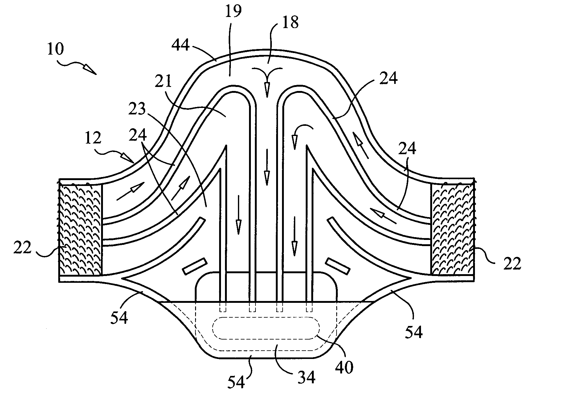
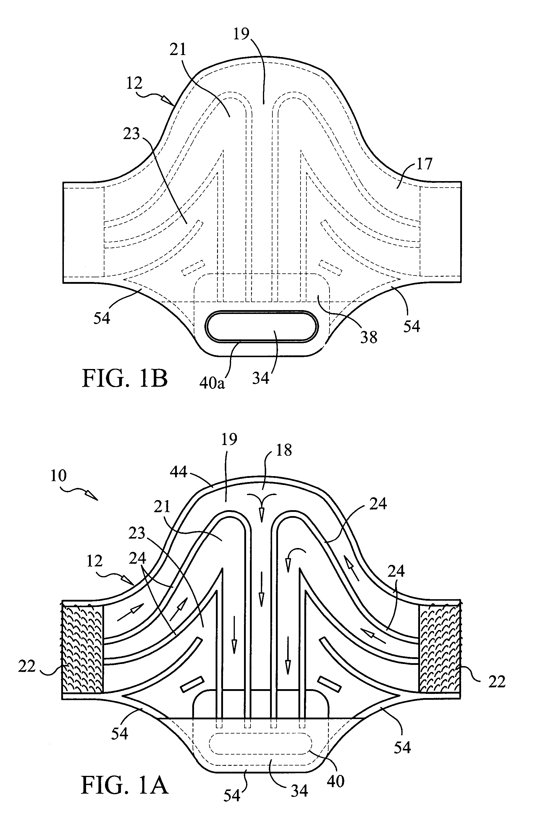
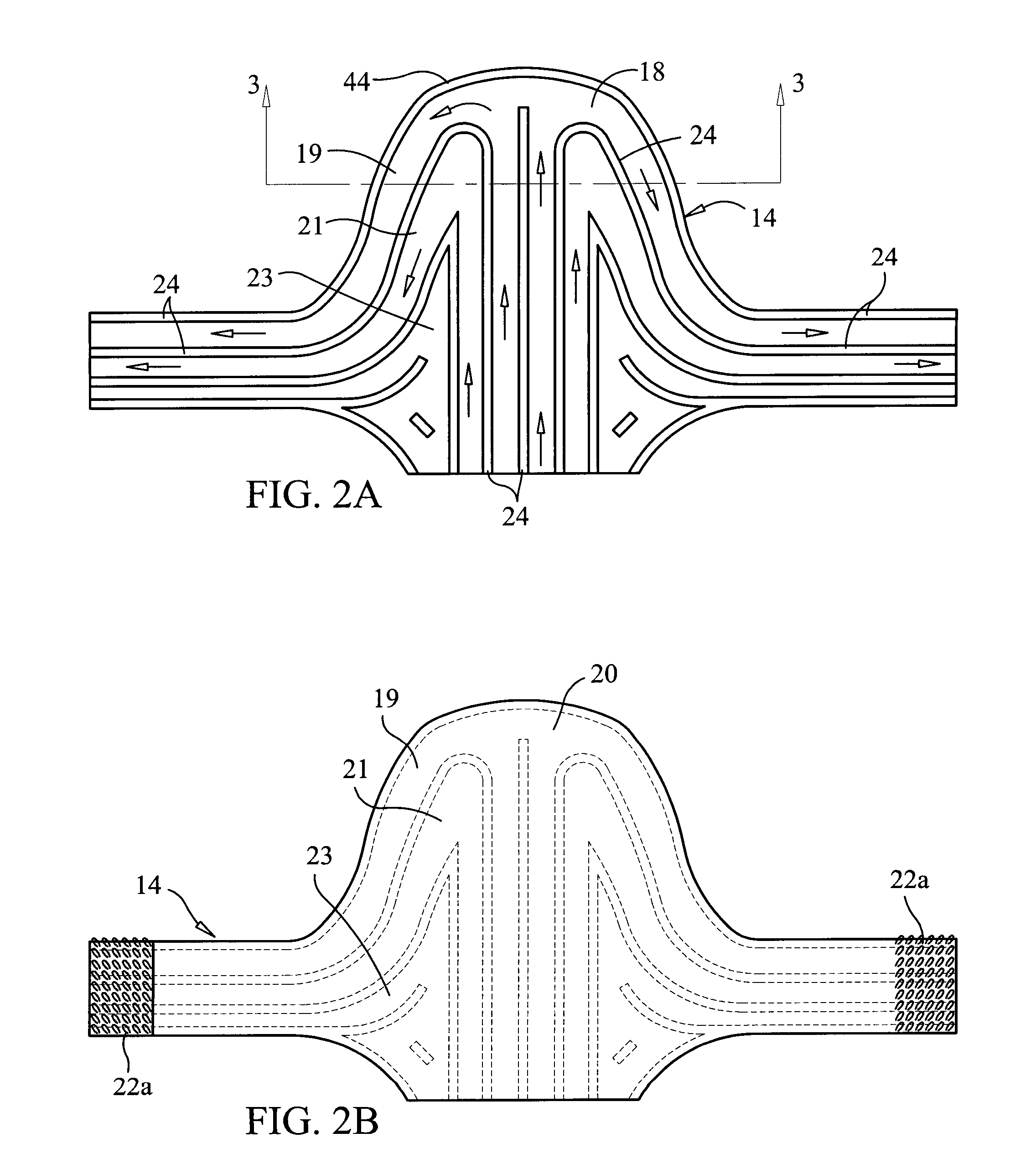
[0033] With reference to the drawings, FIGS. 1A and 1B show the inside and outside of the chest cover section of the garment body respectively of the invention 10. The use of a tee shirt under the cooling garment is preferred for wicking perspiration. As shown in FIGS. 1A and 1B, the cooling garment comprises a chest cover section that has an inside surface shown in FIG. 1A as section 12 having a thin, flexible fabric body 18 made of a stretchable fabric and a plurality of raised, straight and curved, elongated protrusions 24 made of flexible closed cell foam that are glued and / or sewn on one side of the fabric body 18. The adjacent raised protrusions 24 are arranged somewhat parallel to form individual air channels 19, 21 and 23. A fabric baffle area 34 at the base of the chest section 12 connects the air channels together in air flow to the fan intake and is located on the side opposite the fan intake as shown in FIG. 1B. Garment air exhaust port inlet 40a is connected to a fan no...


PUM


Abstract

A garment for cooling a human being wearing a protective vest, comprising a sheet of stretchable material with an inner surface and an outer surface and a plurality of ridge-and-channel ribs forming air channels on the inner surface directed generally toward a wearer. The cooling garment further comprises a detachable air exhaust fan and power supply. The garment may have two or more connectable sections. The ribs are connected to the inner surface, and are made of a moisture resistant material, such as polyethylene. The sheet material is stretchable to conform to the body contours to aid in the air flow through the air channels.

Description

BACKGROUND OF INVENTION [0001] 1. Field of the Invention [0002] The present invention relates generally to a body cooling garment, and, more particularly, to a garment that provides a person wearing a bullet proof vest or other protective vest, cooling air on the skin areas under the bullet proof vest. [0003] 2. Description of Related Art [0004] Bullet proof vests and other protective garments have become a necessity for law enforcement and military personnel. These vests are made of heavy duty, strong materials that insulate and generally restrict air flow from the portions of the body which the vests cover. The body protected areas are generally the chest, back and sides. The vests tend to trap body heat and cause perspiration to accumulate. The resulting body heating and wetness is undesirable and uncomfortable to the wearer, and may cause the vest to degrade and fail prematurely. The degradation is especially dangerous to the wearer because the degradation is not obvious to a we...

Claims


Application Information

Patent Timeline
IPC IPC(8): A41B1/00A41D1/00A41D13/002A41D13/005
CPCA41D13/0053A41D13/0025
Inventor MCCARTER, WALTER K.HAYDEN, JAMES ROBERT III
Owner MCDOUGALL GREGORY A SR
Why Eureka
Try Eureka