Electric vacuum cleaner
a vacuum cleaner and electric technology, applied in the field of electric vacuum cleaners, can solve the problems of frequent maintenance of the filter, easy clogging of the filter in the dust collecting section, etc., and achieve the effect of reducing time and labor
- Summary
- Abstract
- Description
- Claims
- Application Information
AI Technical Summary
Benefits of technology
Problems solved by technology
Method used
Image
Examples
first embodiment
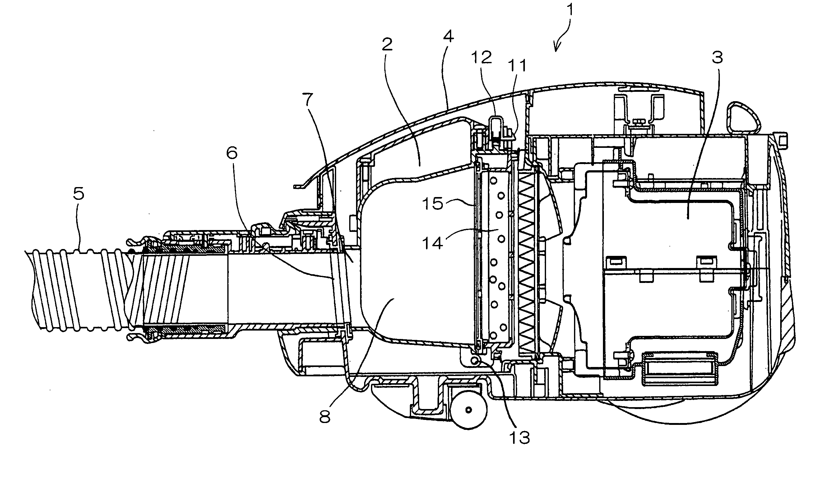
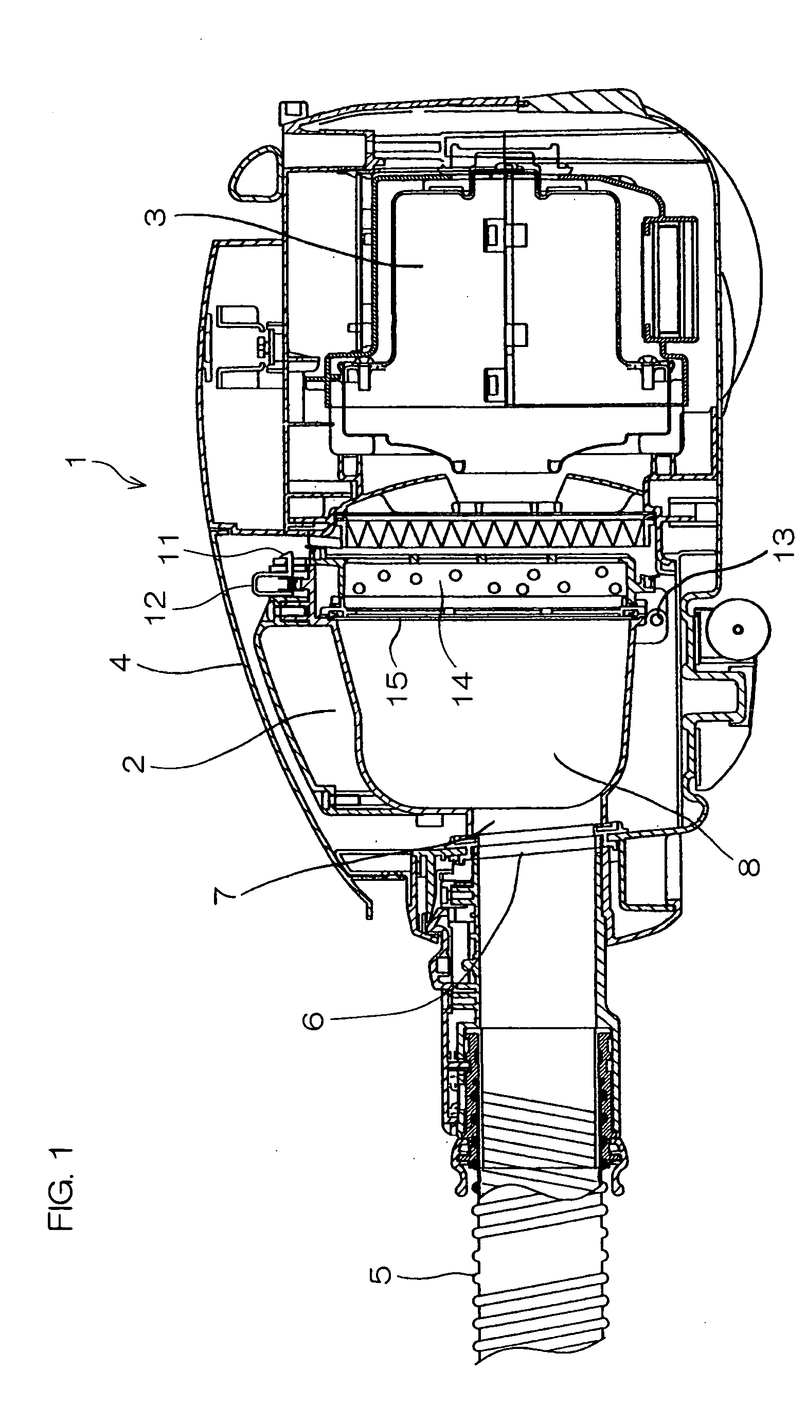
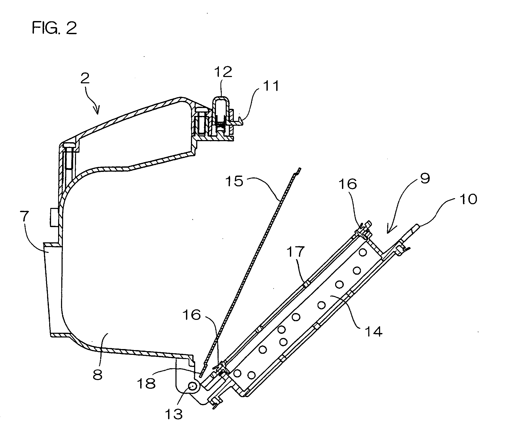
[0069] A first embodiment of an electric vacuum cleaner according to the present invention will be described in detail below on the basis of FIGS. 1 to 4. A cleaner main body 1 of the electric vacuum cleaner comprises a dust collecting section 2 for collecting dust and an electric air blower 3 in its inner part. An upper part of the dust collecting section 2 is covered with a main body dust cover 4 provided in the cleaner main body 1 so as to be capable of being opened and closed. The dust collecting section 2 can be attached to and detached from the cleaner main body 1 with the main body dust cover 4 opened. A suction flow inlet 6 communicating with the dust collecting section 2 is formed in the cleaner main body 1 (see FIG. 1), and a hose 5 is detachably connected to the suction flow inlet 6.
[0070] The dust collecting section 2 comprises a suction port 7 communicating with the suction flow inlet 6, a dust collecting chamber 8 storing dust sucked from the suction port 7, an openin...
second embodiment
[0080] FIGS. 8 to 13 illustrate a second embodiment of the present invention. The same constituent elements as those in the first embodiment are assigned the same reference numerals and hence, the description thereof is not repeated.
[0081] A disposable filter 15a in the second embodiment is formed in a bag shape, as shown in FIG. 8. An opening / closing section 9 is separable into a pre-filter section 20 and a main filter section 21. A coarse-meshed pre-filter 22 is disposed in the pre-filter section 20. A filter 14 composed of urethane or the like is disposed in the main filter section 21. The pre-filter section 20 and the main filter section 21 are rotatable around a rotating shaft 13, and the pre-filter section 20 and the main filter section 21 cover a dust collecting chamber 8 in a state where they are opposed to each other with the opening / closing section 9 closed.
[0082] The bag-shaped disposable filter 15a overlays the pre-filter section 20 from the opposite side of the rotati...
third embodiment
[0090] FIGS. 15 to 31 illustrate a third embodiment of the present invention. The same constituent elements as those in the first and second embodiments are assigned the same reference numerals and hence, the description thereof is not repeated. In the third embodiment, an example of the configuration of positioning means in a disposable filter 15 will be described.
[0091] In a configuration shown in FIGS. 15 to 17, a disposable filter 15 is formed with an approximately rectangular notch 25 in correspondence with a rotating shaft 13 in an opening / closing section 9. As shown in FIG. 15, the disposable filter 15 is positioned by the rotating shaft 13 by being so arranged that the rotating shaft 13 enters the notch 25, and the position of the disposable filter 15 is determined. Therefore, the disposable filter 15 can be reliably positioned on the upstream side of the filter 14 without shifting the position thereof. Further, the rotating shaft 13 for rotating the opening / closing section...
PUM
 Abstract
Description
Claims
Application Information
 - R&D
- Intellectual Property
- Life Sciences
- Materials
- Tech Scout
- Unparalleled Data Quality
- Higher Quality Content
- 60% Fewer Hallucinations
Browse by: Latest US Patents, China's latest patents, Technical Efficacy Thesaurus, Application Domain, Technology Topic, Popular Technical Reports.
© 2025 PatSnap. All rights reserved.Legal|Privacy policy|Modern Slavery Act Transparency Statement|Sitemap|About US| Contact US: help@patsnap.com


