Electrokinetic delivery systems, devices and methods

Inactive Publication Date: 2005-11-10
TELEFLEX LIFE SCI PTE LTD
View PDF65 Cites 72 Cited by
  • Summary
  • Abstract
  • Description
  • Claims
  • Application Information

AI Technical Summary

Benefits of technology

[0006] Generally, the present invention contemplates the use of controlled electrokinetic fluid flow techniques for efficient, reliable and highly precise movem

Problems solved by technology

However, with most conventional diagnostic and therapeutic medical systems, precise movement of large and small aqueous volumes of drugs and other bio-fluids is difficult to achieve.
This difficulty arises because conventional systems employ mechanical components to effect fluid transport and delivery.
Re-configuration of these systems, to enable highly precise movement of small and large aqueous volumes of a solution containing biomaterials, would be i

Method used


Image

  • Electrokinetic delivery systems, devices and methods
  • Electrokinetic delivery systems, devices and methods
  • Electrokinetic delivery systems, devices and methods

Examples


Embodiment Construction

[0067] The invention described herein provides EK systems for efficient, reliable and precise movement of a pump fluid for drug delivery and / or analyte sampling. Before describing these systems, the designs and characteristics of a few exemplary EK pumps suitable for use in said systems are provided below.

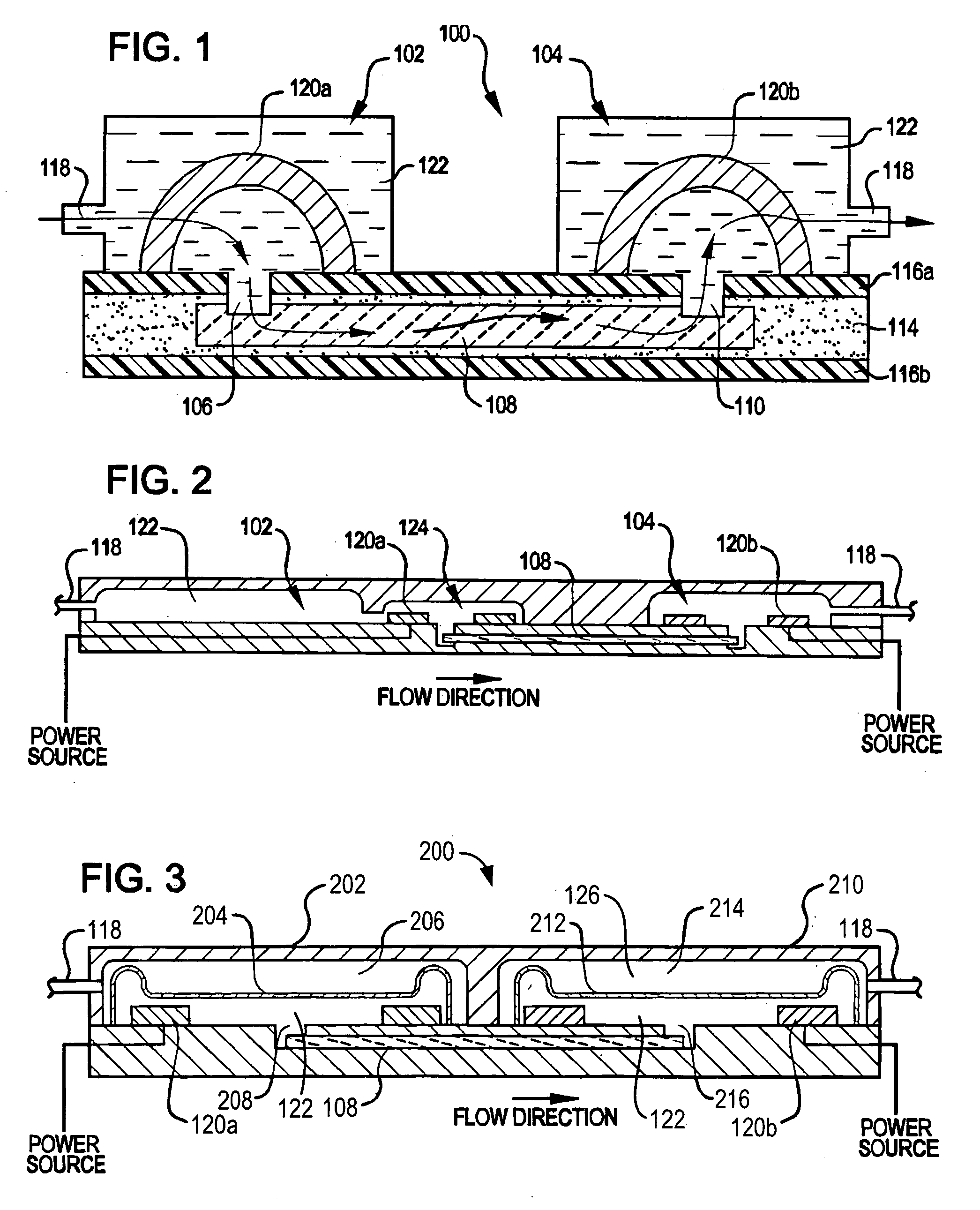
[0068]FIG. 1 is a cross-sectional view of a small, compact EK pump 100. In this example, EK pump 100 comprises a first fluid reservoir 102 and a second fluid reservoir 104. First fluid reservoir 102 is coupled to second fluid reservoir 104 by through-vias 106, 110 and porous dielectric material 108. Through-vias 106 and 110, along with porous dielectric material 108, provide a fluidic path between first reservoir 102 and second reservoir 104. In this example, porous dielectric material 108 is encapsulated within a bonding material 114, between upper and lower substrates 116a and 116b, respectively, as further described in Ser. No. 10 / 198,223.

[0069] Each fluid reservoir further co...


PUM

PropertyMeasurementUnit
Fractionaaaaaaaaaa
Fractionaaaaaaaaaa
Fractionaaaaaaaaaa

Abstract

A method of pumping fluid including the steps of providing an electrokinetic pump comprising a pair of double-layer capacitive electrodes having a capacitance of at least 10−2 Farads/cm2 and being connectable to a power source, a porous dielectric material disposed between the electrodes and a reservoir containing pump fluid; connecting the electrodes to a power source; and moving pump fluid out of the reservoir substantially without the occurrence of Faradaic processes in the pump. The invention also includes an electrokinetic pump system having a pair of double-layer capacitive electrodes having a capacitance of at least 10−2 Farads/cm2; a porous dielectric material disposed between the electrodes; a reservoir containing pump fluid; and a power source connected to the electrodes; the electrodes, dielectric material and power source being adapted to move the pump fluid out of the reservoir substantially without the occurrence of Faradaic processes in the pump.

Description

CROSS-REFERENCE [0001] This application is a continuation-in-part application of appl. Ser. No 10 / 273,723, filed Oct. 18, 2002; appl. Ser. No. 10 / 322,083, filed Dec. 17, 2002; appl. Ser. No. 10 / 198,223, filed Jul. 17, 2002; and PCT application PCT / US2003 / 032895, filed Oct. 17, 2003, which are incorporated herein by reference in their entirety and to which we claim priority under 35 USC § 120. This application also claims benefit under 35 USC § 119 of appl. Ser. No. 60 / 564,497, filed Apr. 21, 2004, which is also incorporated herein by reference in its entirety.BACKGROUND OF THE INVENTION [0002] In many diagnostic and therapeutic medical applications (including drug delivery and analyte sampling / monitoring), precise transport of a drug, blood and / or other bio-fluid is important. However, with most conventional diagnostic and therapeutic medical systems, precise movement of large and small aqueous volumes of drugs and other bio-fluids is difficult to achieve. This difficulty arises bec...

Claims


Application Information

Patent Timeline
IPC IPC(8): A61M5/142A61M5/145A61M5/148A61M5/172B67D99/00F04B19/00F04B43/04
CPCA61M5/14248A61M5/14276A61M5/1483A61M5/1723F04B43/043A61M2205/52A61M2230/201F04B19/006A61M2005/14513Y10T137/0357Y10T137/218Y10T137/0379Y10T137/0318Y10T137/0368
Inventor ANEX, DEON S.PAUL, PHILLIP H.NEYER, DAVID W.HLAVKA, EDWIN J.
Owner TELEFLEX LIFE SCI PTE LTD
Why Eureka
Try Eureka