
Method for assessing interfering noise

Active Publication Date: 2005-11-10
BAYERISCHE MOTOREN WERKE AG +1
View PDF5 Cites 7 Cited by
  • Summary
  • Abstract
  • Description
  • Claims
  • Application Information

AI Technical Summary

Benefits of technology

[0021] An overall assessment of the noise and a differentiation between an acceptable and an unacceptable noise behavior can be achieved in a part

Problems solved by technology

Here also, only a limited diagnosis of the noise source can be made.
The previous methods relate to the problem of identifying the cause of interfering noises of different components in the motor vehicle.
Apart from the fact that in this case also possibly interfering n

Method used


Image

  • Method for assessing interfering noise
  • Method for assessing interfering noise
  • Method for assessing interfering noise

Examples


Example

DETAILED DESCRIPTION OF THE DRAWINGS

[0028] The starting point for the analyzing method according to the invention is the fact that a total noise is composed of a (quasi)stationary background noise (noise, wind, production sounds) and the unsteady interfering noises to be detected. The background noise is frequently exhibited as an offset in a sound level-time variation diagram.

[0029] The human ear reacts very sensitively to “changes”. However, changes in the overall level (sum over all frequencies) are not sufficient in order to feel that a noise is interfering. On the contrary, a noise is perceived as being interfering when its tonal composition changes. The invention takes this into account in that the tonal composition is detected.

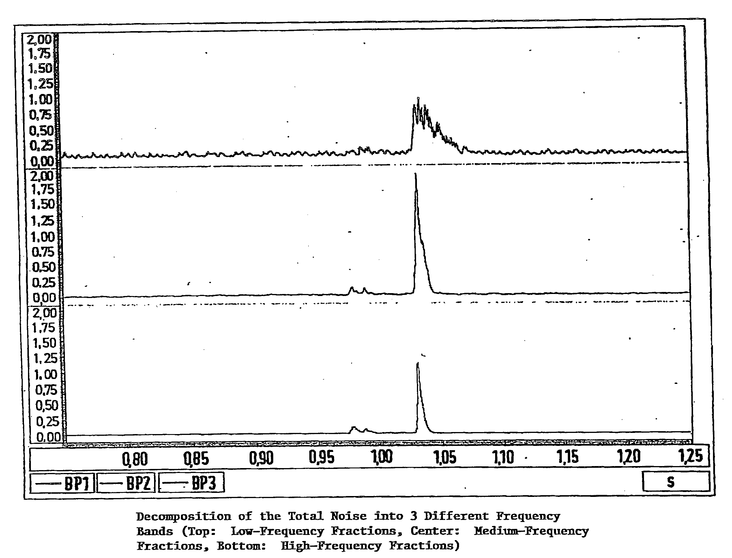
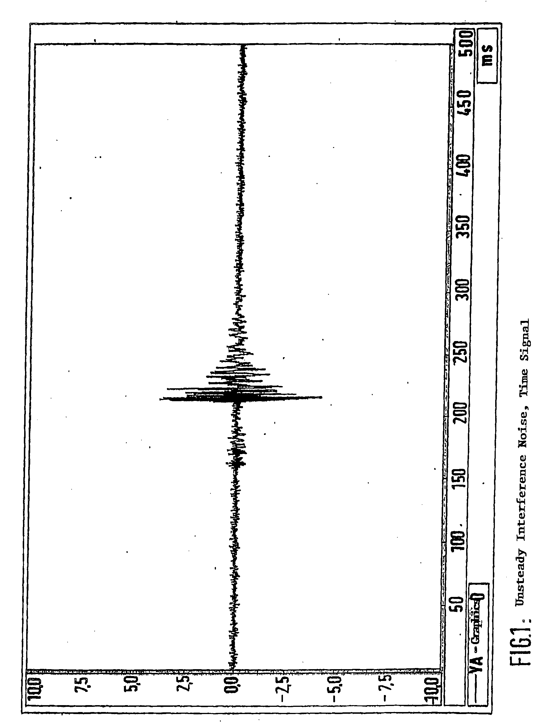
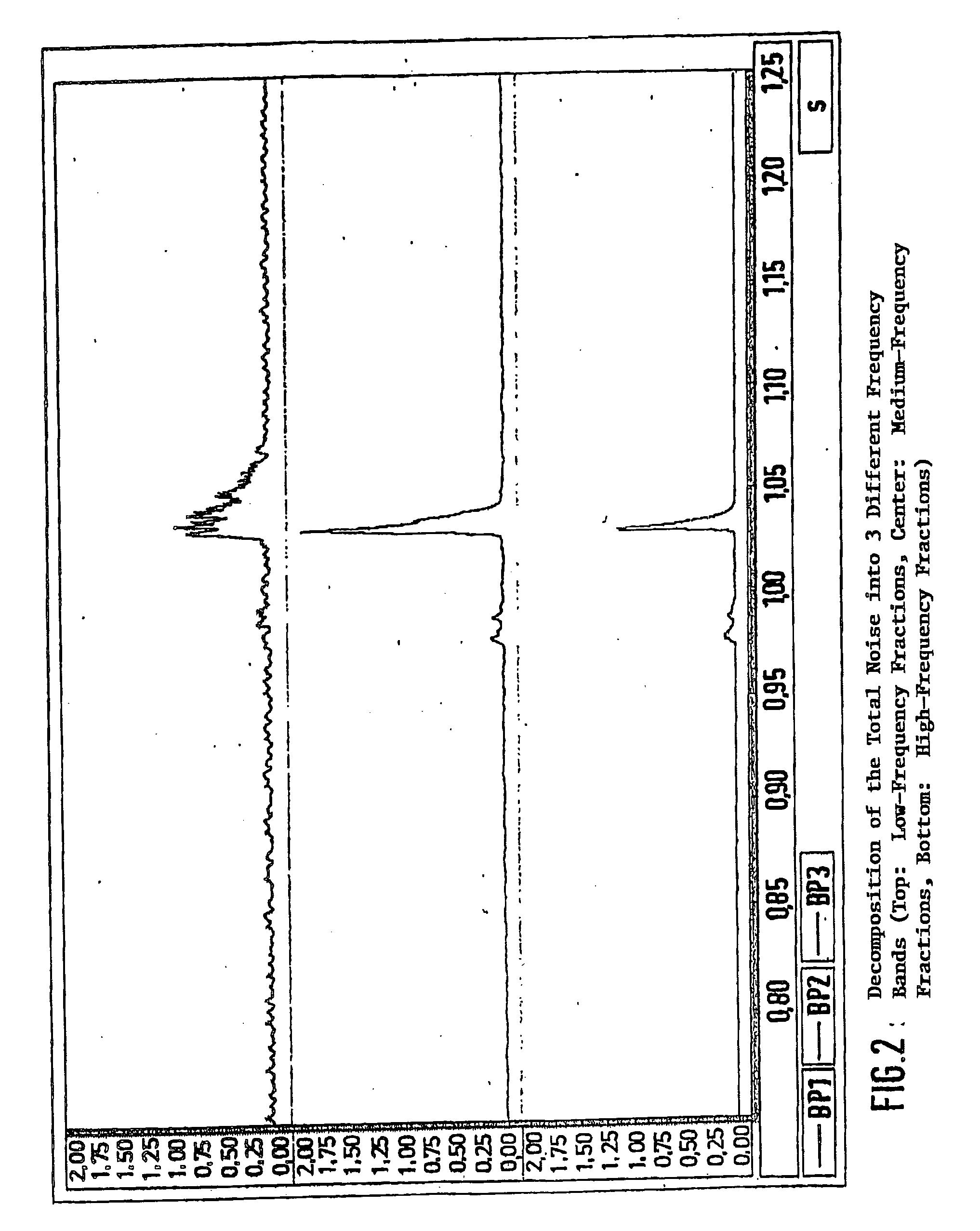
[0030] For this purpose, a noise, which is illustrated as an example in FIG. 1 and is recorded over a defined measuring time, is decomposed into different (here, three) frequency bands (low-frequency, medium-frequency and high-frequency fraction).

[0...


PUM


Abstract

The invention relates to a method for assessing interfering noise in motor vehicles, according to which noise occurring during a predefined measuring time is divided into different frequency ranges, the changes in level relative to the background noise are determined within said frequency ranges, and the determined changes in level are evaluated.

Description

CROSS-REFERENCE TO RELATED APPLICATIONS [0001] This application is a continuation of PCT Application No. PCT / EP2003 / 011800 filed on Oct. 24, 2003, which claims priority to German Application No. 102 50 739.2 filed Oct. 31, 2002.BACKGROUND AND SUMMARY OF THE INVENTION [0002] The invention relates to a method of assessing interfering noise in motor vehicles. Noises of this type occur, for example, during a rubbing motion of material surfaces. [0003] In connection with the diagnosis of motor vehicle functions, a method of determining an adhering-sliding motion is known from German Patent document DE 197 23 728 A1. This known method relates essentially to the capability to differentiate between a normal condition and an adhering-sliding of moving working elements, such as control valves. [0004] Furthermore, a method of determining components of a vehicle unit which are in need of repair is known from German Patent document DE 34 37 661 A1. In the case of this method, vehicle units are m...

Claims


Application Information

Patent Timeline
IPC IPC(8): G01H1/00G01H3/00
CPCG01H3/00G01H1/00
Inventor STEINBERG, KLAUSACHTEN, TOBIAS
Owner BAYERISCHE MOTOREN WERKE AG
Learn More