
Energy management method, energy management device, switching device for an energy management device, and computer software product

a technology of switching device and energy management device, which is applied in the direction of forecasting, instruments, data processing applications, etc., can solve the problems of inability to save and optimize, inability to provide process automation or process control system, technical and financial expenditure, etc., and achieves the effect of flexible connection and easy integration into existing consumer infrastructures

Inactive Publication Date: 2017-09-28
SIEMENS AG
View PDF0 Cites 0 Cited by
  • Summary
  • Abstract
  • Description
  • Claims
  • Application Information

AI Technical Summary

Benefits of technology

The patent describes an energy management system that allows for the detection of energy consumption in new and existing consumer combinations. The system can detect consumption for various energy forms such as electricity, gas, and liquid chemical energy carriers. The system can be used in industrial installations, buildings, or parts of buildings. The system includes a central device and a switching device that can be synchronized using network clocks. The switching device can be connected to different detection devices using an adapter element, making it easier to integrate into existing consumer infrastructures. The technical effect of the patent is to provide a flexible and cost-effective solution for energy management and consumption detection.

Problems solved by technology

However, these potentials for saving and optimization are frequently not possible without a precise knowledge of consumption profiles of consumers and a detailed data evaluation.
In smaller industrial installations or buildings however, frequently no process automation or process control system is provided.
Depending on how the specific consumer infrastructure is configured, possibly only fractions of the functional scope of a process automation or process control system may be used, which is why the technical and financial expenditure for installing such a system is not expedient in all consumer combinations.
These special solutions are technically very complex, e.g., a retrofitting of suitably adapted sensors in existing consumer combinations.

Method used


Image

  • Energy management method, energy management device, switching device for an energy management device, and computer software product
  • Energy management method, energy management device, switching device for an energy management device, and computer software product
  • Energy management method, energy management device, switching device for an energy management device, and computer software product

Examples


Embodiment Construction

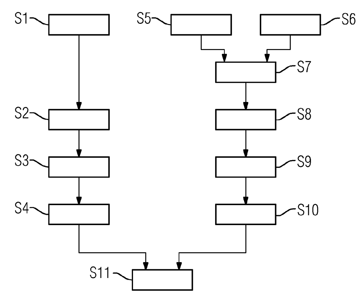
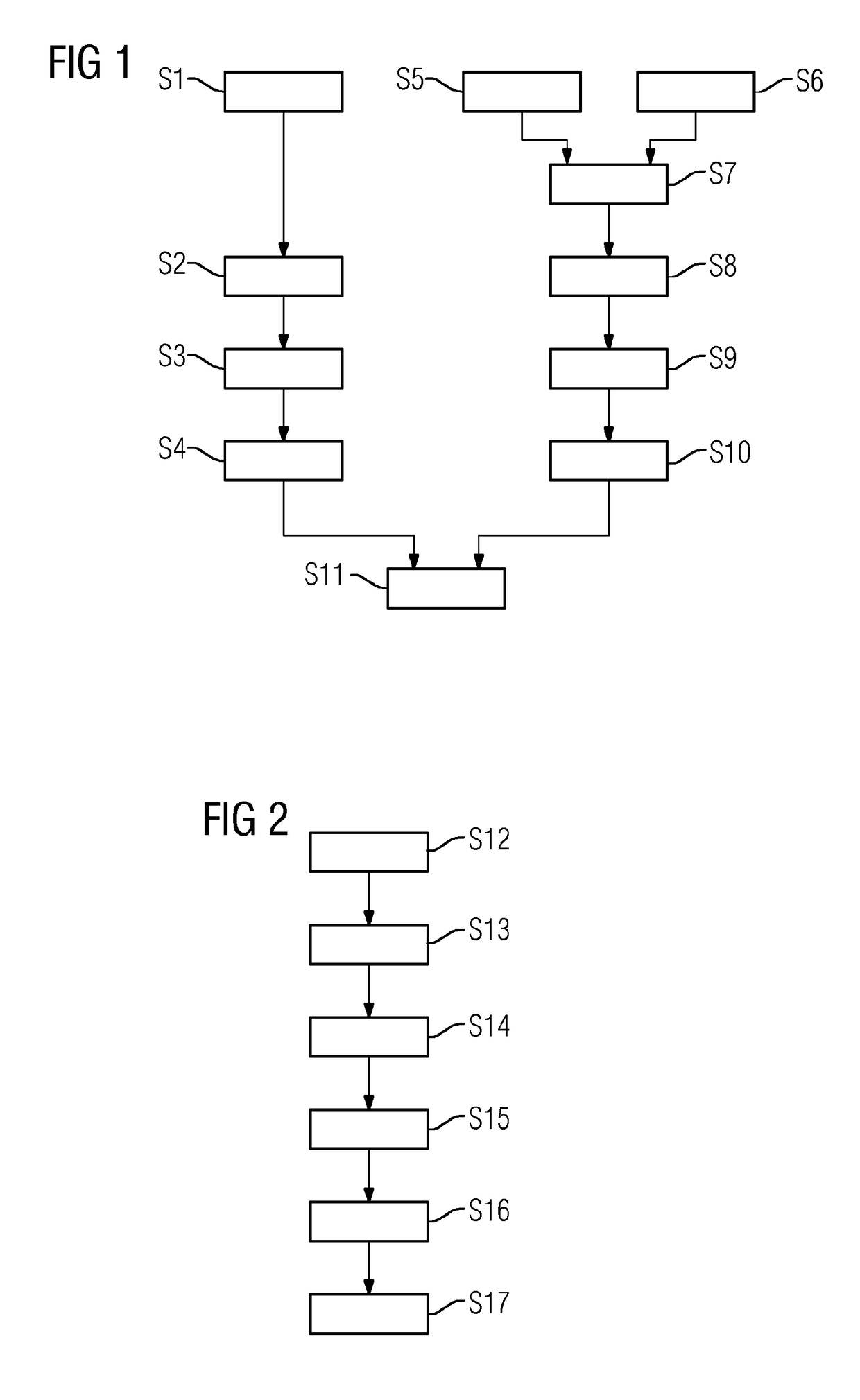
[0048]FIG. 1 depicts schematically a flow diagram of an energy management method for detecting an energy consumption of a plurality of consumers connected to an energy supply network in a building. In act S1 a detection value relating to an energy consumption is detected by a detection device. The detection value detected in act S1 includes a motor rotational speed, from which an instantaneous motor power and therefore an energy consumption is calculated in the further course of the method.

[0049]The detection value detected in act S1 is provided to a switching device in act S2 with a detection-device-side protocol. The rotational speed of the motor is provided on the detection device side as the frequency of a pulse voltage, which is applied to a signal line supplied to the switching device, e.g., the detection value corresponds to a period length.

[0050]This period length, (e.g., the transmission of the detection value according to the detection-device-side protocol), is detected by...


PUM


Abstract

An energy management method is provided for detecting an energy consumption of at least one consumer connected to an energy supply network, wherein relevant detection values of each energy consumption are detected by a plurality of detection devices and / or calculated from detected values. A switching device is respectively assigned to at least one of the detection devices and / or at least one group of the detection devices. The detection values detected and / or calculated by the detection device and / or the group of detection devices are each provided to the switching device according to a predefined detection device protocol for the detection device and / or the group of detection devices. The respective energy values are transmitted to a central device via a network which connects the central device to all switching devices, according to a predefined central device protocol which differs from the detection device protocol.

Description

[0001]The present patent document is a §371 nationalization of PCT Application Serial Number PCT / EP2015 / 067778, filed Aug. 3, 2015, designating the United States, which is hereby incorporated by reference, and this patent document also claims the benefit of DE 10 2014 216 822.8, filed Aug. 25, 2014, which is also hereby incorporated by reference.TECHNICAL FIELD[0002]The disclosure relates to an energy management method for detecting an energy consumption of at least one consumer connected to an energy supply network, wherein the sum of the maximum power consumptions of all the consumers is at least 5 kW, wherein detection values relating to one energy consumption in each case are detected and / or calculated by a plurality of detection devices, after which at least parts of the detection values and / or values calculated from at least parts of the detection values are transmitted as energy values to a central device and stored there and / or evaluated. In addition, the disclosure relates ...

Claims


Application Information

Patent Timeline
IPC IPC(8): G06Q10/04H02J13/00G06Q50/06
CPCG06Q10/04H02J13/0086G06Q50/06
Inventor BUCHSTALLER, DOMINICHALMUSCHI, NADERJUNGNICKEL, FRANKREINSCHKE, JOHANNESZIEGNER, JOCHEN
Owner SIEMENS AG
Learn More