LED display module

A display module, LED light board technology, applied in the direction of instruments, identification devices, etc., can solve the inconvenience and flexible processing of the hardware connection between the control board and the LED light board, reduce the stability and reliability of signal transmission, and the tightness of the structure of the LED display module. Large and other problems, to achieve the effect of reducing signal transmission connection points, reducing maintenance cost and difficulty, and improving stability and reliability

Inactive Publication Date: 2010-02-03
BEIJING JUSHU DIGITAL TECH DEV
View PDF8 Cites 17 Cited by
  • Summary
  • Abstract
  • Description
  • Claims
  • Application Information

AI Technical Summary

Problems solved by technology

[0006] In addition, if figure 1 The structural tightness of the LED display module shown is relatively large, that is, from figure 1 It can be seen that there are densely arranged pin headers and light points in the display module of the prior art, and this structure is obviously not conducive to heat dissipation
[0007] In the prior art, because there are many connection points between the control board and the LED light board, the stability and reliability of signal transmission are greatly reduced, and it is not convenient to flexibly handle the hardware connection mode between the control board and the LED light board. It brings difficulties to production and processing, and brings great difficulty to later maintenance, inspection and disassembly work

Method used


Image

  • LED display module
  • LED display module
  • LED display module

Examples


Embodiment 1

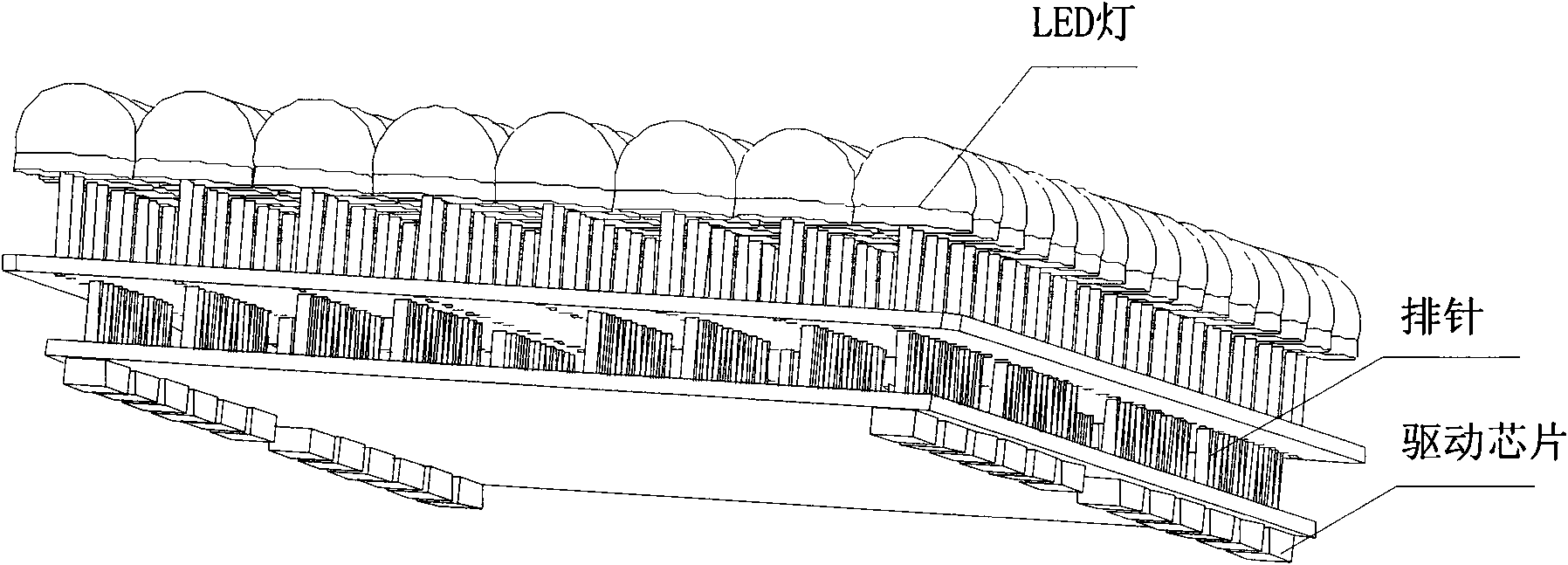
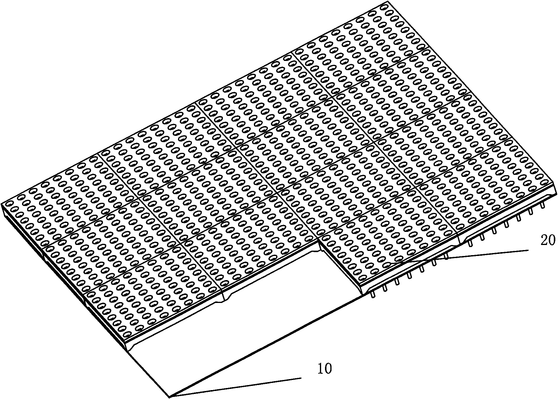
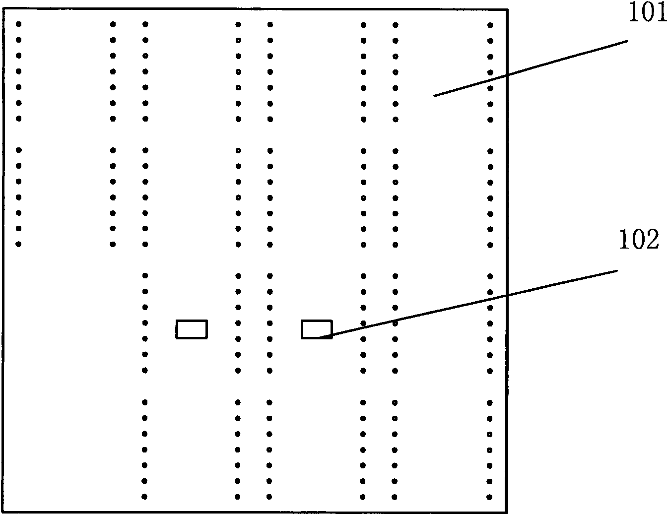
[0034] This embodiment provides an LED display module, refer to figure 2 , image 3 , Figure 4 and Figure 5 , including: a control board 10 and at least one LED lamp board 20, the control board 10 includes a first PCB board 101 and a control circuit 102, and the control circuit is used to send the LED lamp board to the LED lamp board through the first PCB board 101 20 provides control signals, the LED lamp board 20 includes a second PCB board 206, a column driver circuit 205 and LED pixel points 201, the LED pixel points 201 are placed on the front side of the second PCB board 206, and the column driver circuit The circuit is placed on the back of the second PCB board 206 to receive the control signal and drive the LED pixel 201 to emit light according to the control signal; thus, the present invention transfers the column drive circuit 205 to the LED lamp board Above, the position of the drive circuit on the original control board 10 can be hollowed out or no components...

Embodiment 2

[0037] On the basis of Embodiment 1, preferably, the LED light board described in this embodiment includes 64 LED pixels, and the 64 LED pixels form a square array of 8 by 8, such as Figure 4 The LED light board shown is composed of 64 identical LED pixel points 201 to form an 8 by 8 square array. Such a square array is convenient for installation and use.

[0038] Or, preferably, the above-mentioned LED pixels are composed of at least one blue LED, at least one red LED, and at least one green LED, and the above-mentioned LEDs can be LED lamps of any shape and any package structure as required.

[0039] Or, preferably, this embodiment integrates a sealed light-transmitting mask 202 on the LED lamp board 20. The lampshade is a sealed and waterproof structure, and contains 64 through holes on its surface. The mask is sealed and fixed on the second PCB board. Together, in this way, each through hole accommodates an LED pixel, injects transparent material into the through hole, a...

Embodiment 3

[0042] On the basis of the above-mentioned embodiments, preferably, in this embodiment, the sealing light-transmitting mask 203 is extended to form a support portion 203 along the normal direction of the back of the second PCB board 206, that is, the direction perpendicular to the second PCB board , the supporting part 203 is used to support the LED lamp board 20 when the LED lamp board 20 is installed on the control board 10, so that the LED lamp board 20 will not shake left and right, up and down.

[0043] Furthermore, in a preferred example, four supporting parts 203 can be set, and the above-mentioned supporting parts 203 are arranged on the four legs of the sealed light-transmitting mask 202, such as Figure 4 As shown in , at the same time, the above-mentioned support part 203 can be higher than the back of the above-mentioned sealed light-transmitting mask 202, so that after installation, a gap can be left between the LED lamp board 20 and the control board 10 to facilit...


PUM


Abstract

The invention discloses an LED display module, comprising a control board and at least one LED lamp panel, wherein, the control board comprises a first PCB and a control circuit, and the control circuit is used for providing control signal to the LED lamp panel by the first PCB; and the LED lamp panel comprises a second PCB, a column drive circuit and LED pixel points, the LED pixel points are arranged on the front face of the second PCB, and the column drive circuit is arranged on the rear face of the second PCB for receiving the control signal and driving the LED pixel points to illuminate according to the control signal. The LED display module greatly reduces signal transmission connecting points between the control board and the LED lamp panel, improves stability and reliability of signal transmission, solves the problem of heat dissipation of the whole LED display module structure, saves PCB materials and reduces the weight of the whole LED display module.

Description

technical field [0001] The invention relates to the field of LED display, in particular to an LED display module. Background technique [0002] At present, the row and column driving circuits of the LED display module are all designed on the control board. The LED display module is connected by the control board and multiple LED dot matrix light-emitting modules through the pin row. The pin row plays the role of fixing and transmitting signals at the same time. [0003] Such as figure 1 Shown is a schematic diagram of the structure of the LED display module in the prior art. The LED lights are arranged in an array on the PCB board to form an LED light board. The LED lights are electrically connected to the driver chip on the control board through pin headers. Each single lamp (static) or each column of lamps (scanning) on ​​the light-emitting module needs a column control signal, plus the row drive signal required for each row, so the LED dot matrix light-emitting module ne...

Claims


Application Information

Patent Timeline
Patent Type & Authority Applications(China)
IPC IPC(8): G09F9/33
Inventor 徐微邵寅亮郑丹梅
Owner BEIJING JUSHU DIGITAL TECH DEV
Why Eureka
Try Eureka