Clutch-brake combination mechanism

A combination mechanism and clutch technology, applied in the combination of coupling and brake, gear transmission mechanism, mechanical equipment, etc., to achieve the effect of high torque

Inactive Publication Date: 2017-08-15
德国奥特林豪斯公司
View PDF6 Cites 0 Cited by
  • Summary
  • Abstract
  • Description
  • Claims
  • Application Information

AI Technical Summary

Problems solved by technology

[0007] It must also be considered here that the current construction is only capable of a specific, lim

Method used


Image

  • Clutch-brake combination mechanism
  • Clutch-brake combination mechanism

Examples


Embodiment Construction

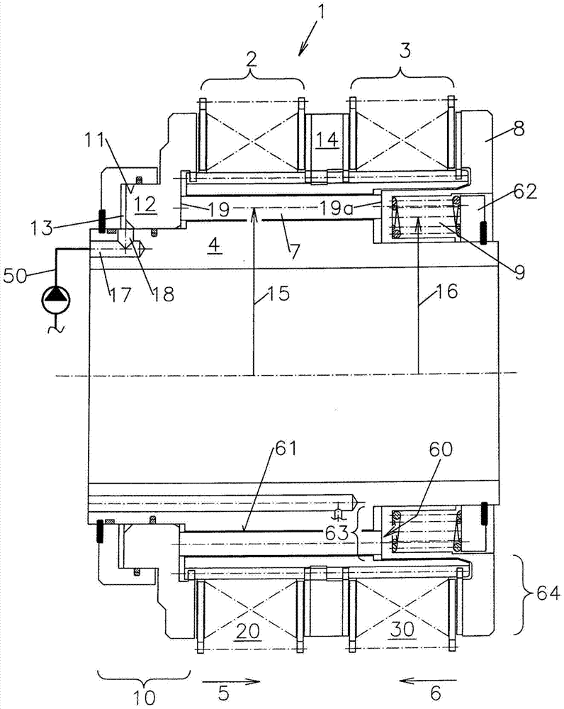
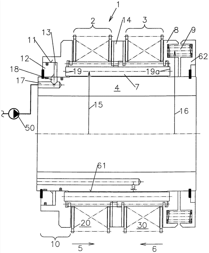
[0039] The figures show a clutch-brake combination 1 according to the invention.

[0040] At one end of the common carrier 4 there is a clutch disc pack 2 and at the other end of the common carrier 4 there is a brake disc pack 3 .

[0041] The clutch plates and brake plates are formed in the form of a ring and include teeth on their inner circumference by means of which the clutch plates and brake plates sit on corresponding teeth provided on the outer circumference of the carrier 4 and are thus axially The way to move is located on the outer periphery of the carrying device 4 .

[0042] The clutch 20 is acted upon by the piston-cylinder unit 10 in the closing direction 5 , and if the clutch is closed, the drive of the downstream mechanical components can then be brought about by the teeth of the clutch arranged on the outer circumference.

[0043] For this purpose, the piston-cylinder-unit 10 is equipped with an annular cylinder 11 which is spaced at a distance from the oute...


PUM


Abstract

The invention relates to a clutch-brake combination (1), comprising a hydraulic piston-cylinder unit (10) for closing the clutch (20) and a safety brake (30) which is under the preload of springs (9) in the direction of closure (6) thereof and is vented by means of the piston-cylinder unit (10) against the preload of the springs (9) during the displacement of the clutch in the direction of closure (5). To this effect, a coupling element (7) is provided between the mobile part of the piston-cylinder unit (10) and a pressure piece (8) acting upon the brake (30) in the direction of closure (6) thereof, wherein the springs (9) are located on the side of the safety brake (30) of the support (4) that receives the respective packets (2, 3) of clutch plates or brake plates, while the coupling elements (7) are pressure pins which extend axially from the side of the clutch (20) to the side of the safety brake (30) through the support.

Description

technical field [0001] The invention relates to a clutch-brake combination according to the preambles of the independent claims. Background technique [0002] Such clutch-brake combinations are well known. [0003] Usually, in such a clutch-brake combination, the clutch plate set or the brake plate set is arranged on a carrier device. The clutch pack is pressed together by a hydraulic piston-cylinder-unit. Here, too, a hydraulic force is applied against the spring prestress, which is necessary in order to press the brake disc pack together during the necessary braking process without any other influence from the outside. [0004] Such a device is used, for example, in stamping machines for the manufacture of body parts, to keep the plunger safely open for changing workpieces after a lift performed by a closed clutch, so that the next lift can then be performed. [0005] What is therefore important in these clutch-brake-combinations is the cooperation of the two sub-units ...

Claims


Application Information

Patent Timeline
IPC IPC(8): F16D67/04
CPCF16D67/04F16D2121/02F16D2121/12
Inventor 赫伯特·赛格尔
Owner 德国奥特林豪斯公司
Why Eureka
Try Eureka