Multi-stage liquid distributor

A technology of liquid distributor and distribution box, which is applied in fine chemical industry, petrochemical industry, coal chemical industry, and coking industry. It can solve the problems of uneven distribution, small opening ratio, and few liquid distribution points, so as to improve the efficiency of gas-liquid mass transfer. , Strong anti-clogging ability, uniform liquid distribution

Pending Publication Date: 2022-08-09
TIANJIN CHUANGJU TECHNOLGOY
View PDF0 Cites 0 Cited by
  • Summary
  • Abstract
  • Description
  • Claims
  • Application Information

AI Technical Summary

Problems solved by technology

For example, if the traditional trough-type liquid distributor is used, because the secondary tank is narrow, the liquid level gradient in the tank is very large, resulting in uneven distribution of the liquid flowing out of the distribution holes on the side of the secondary tank; and the opening on the side of the secondary tank is small , it is easy to block the hole, causing the liquid to drift, and the desulfurization effect is not ideal
Another example is the use of a traditional grooved plate liquid distributor, which occupies a large space in the tower body, is heavy, has a small opening ratio, is easy to block, and has uneven distribution points. The supporting beam of this distributor is generally I-beam or H For shaped steel beams, distribution holes cannot be opened on the upper part of the beams, and there is no liquid in the filling directly below the beams, resulting in uneven distribution, thereby reducing the desulfurization efficiency
[0003] In summary, the traditional distributors used in desulfurization towers generally have problems such as few liquid distribution points, uneven distribution, and easy blockage.

Method used


Image

  • Multi-stage liquid distributor
  • Multi-stage liquid distributor
  • Multi-stage liquid distributor

Examples


Embodiment 1

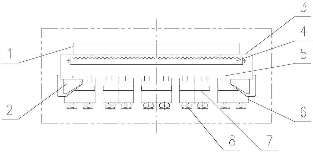
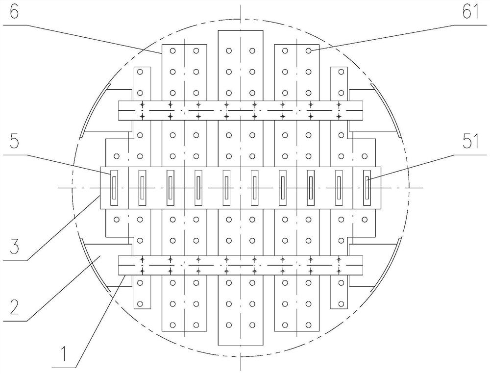
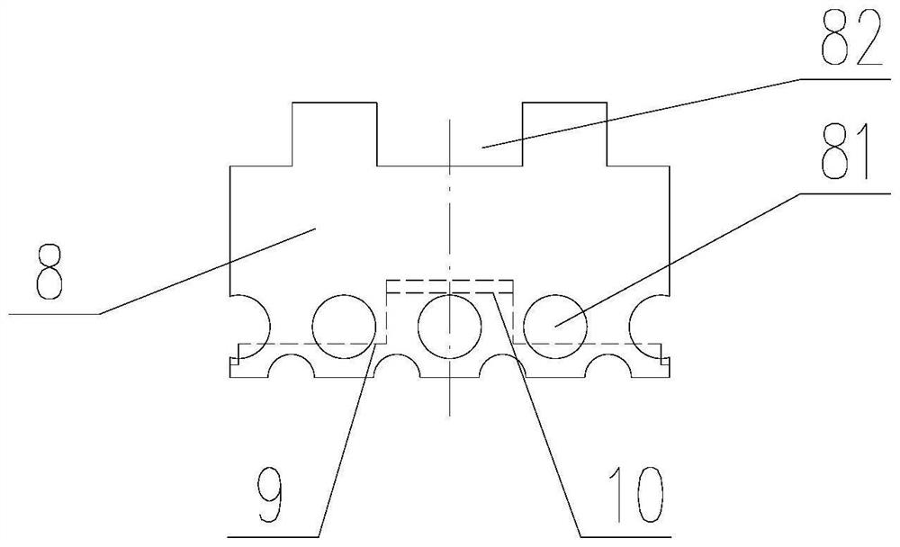
[0036] A multi-stage liquid distributor (distributor for short) is characterized in that, the distributor comprises a support beam 1, a support 2, a primary groove 3, a buffer groove 4, a distribution box 5, a secondary groove 6, a buffer plate 7 and assemblies;

[0037] The support 2 is welded and fixed on the inner side of the tower wall; the two ends of the support beam 1 are detachably fixed on their respective supports 2 through bolts and nuts, parallel to the horizontal plane (that is, the cross-section of the tower); along the cross-sectional direction of the tower , a number of secondary slots 6 are detachably mounted on the bottom of the support beam 1 through bolts and nuts;

[0038] Along the cross-sectional direction of the tower, at least one primary slot 3 is detachably fixed on the tops of all secondary slots 6 through bolts and nuts; each primary slot 3 is provided with a detachable buffer slot 4, located in the primary slot 3. The upper or middle part of the ...


PUM


Abstract

The invention discloses a multi-stage liquid distributor which comprises a support beam, a support, a first-stage groove, a buffer groove, a distribution box, a second-stage groove, a buffer plate and an assembly, a plurality of slotted holes are formed in the bottom of each secondary groove, and an assembly is fixedly mounted below each slotted hole; the assembly consists of a sprayer, a rib plate and a liquid receiving plate; the top of the sprayer is fixed at the bottom of the secondary tank; the liquid receiving plate is fixed on the inner wall of the sprayer through a rib plate and is positioned in the sprayer; a plurality of vent holes are formed in the upper portion of the side wall of the sprayer in the circumferential direction and used for gas phase circulation, and a plurality of liquid distribution holes are formed in the lower portion of the side wall in the circumferential direction and used for liquid phase circulation. According to the invention, four-stage distribution of liquid is realized, and three-stage distribution of the liquid receiving plate and four-stage distribution of the sprayer are added, so that the efficiency of the desulfurizing tower is greatly improved. The liquid distributor has multiple liquid distribution points and is uniform in distribution. The anti-clogging agent is high in anti-clogging capacity.

Description

technical field [0001] The invention relates to the fields of coking, coal chemical industry, petrochemical industry and fine chemical industry, in particular to a multistage liquid distributor. Background technique [0002] In the fields of coking, coal chemical industry, fertilizer industry and other fields, the desulfurization tower is the key equipment in the desulfurization section. Since the desulfurization liquid contains medium oil, dust and sulfur elemental solids, etc., long-term operation can easily lead to blockage. In addition, the efficiency of the desulfurization tower is mainly affected by the distributor and packing. When the desulfurization tower is running, the desulfurization liquid volume is very large, and there are some common problems with the traditional distributor. For example, using a traditional tank type liquid distributor, due to the narrow secondary tank, the liquid level gradient in the tank is large, resulting in uneven distribution of the...

Claims


Application Information

Patent Timeline
Patent Type & Authority Applications(China)
IPC IPC(8): B01D53/79B01D53/48
CPCB01D53/79B01D53/48
Inventor 王柱祥商恩霞
Owner TIANJIN CHUANGJU TECHNOLGOY
Why Eureka
Try Eureka