Electrical connector

a technology of electrical connectors and connectors, applied in the direction of coupling device connection, coupling parts engagement/disengagement, connection contact member materials, etc., can solve the problem of substantial time expenditure associated with disengaging particular threaded joints

Active Publication Date: 2005-11-10
PHOENIX CONTACT GMBH & CO KG
View PDF18 Cites 23 Cited by
  • Summary
  • Abstract
  • Description
  • Claims
  • Application Information

AI Technical Summary

Benefits of technology

[0013] The construction allows for the use of complete screw threads and thus the combinati

Problems solved by technology

In addition, in the event of malfunctions of the machine and replacement of broken-down components, sensors, or electronic devices, their connecting lines must be quickly disconnected

Method used


Image

  • Electrical connector
  • Electrical connector
  • Electrical connector

Examples


Embodiment Construction

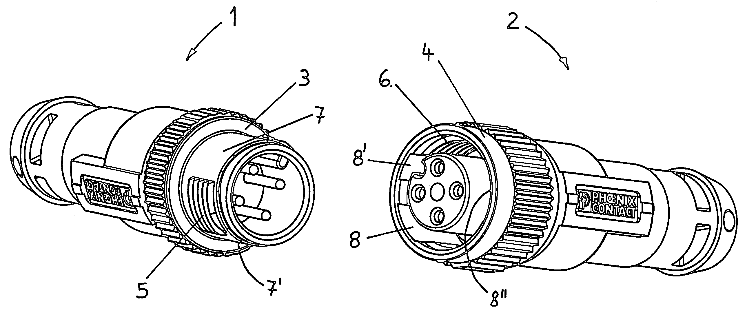
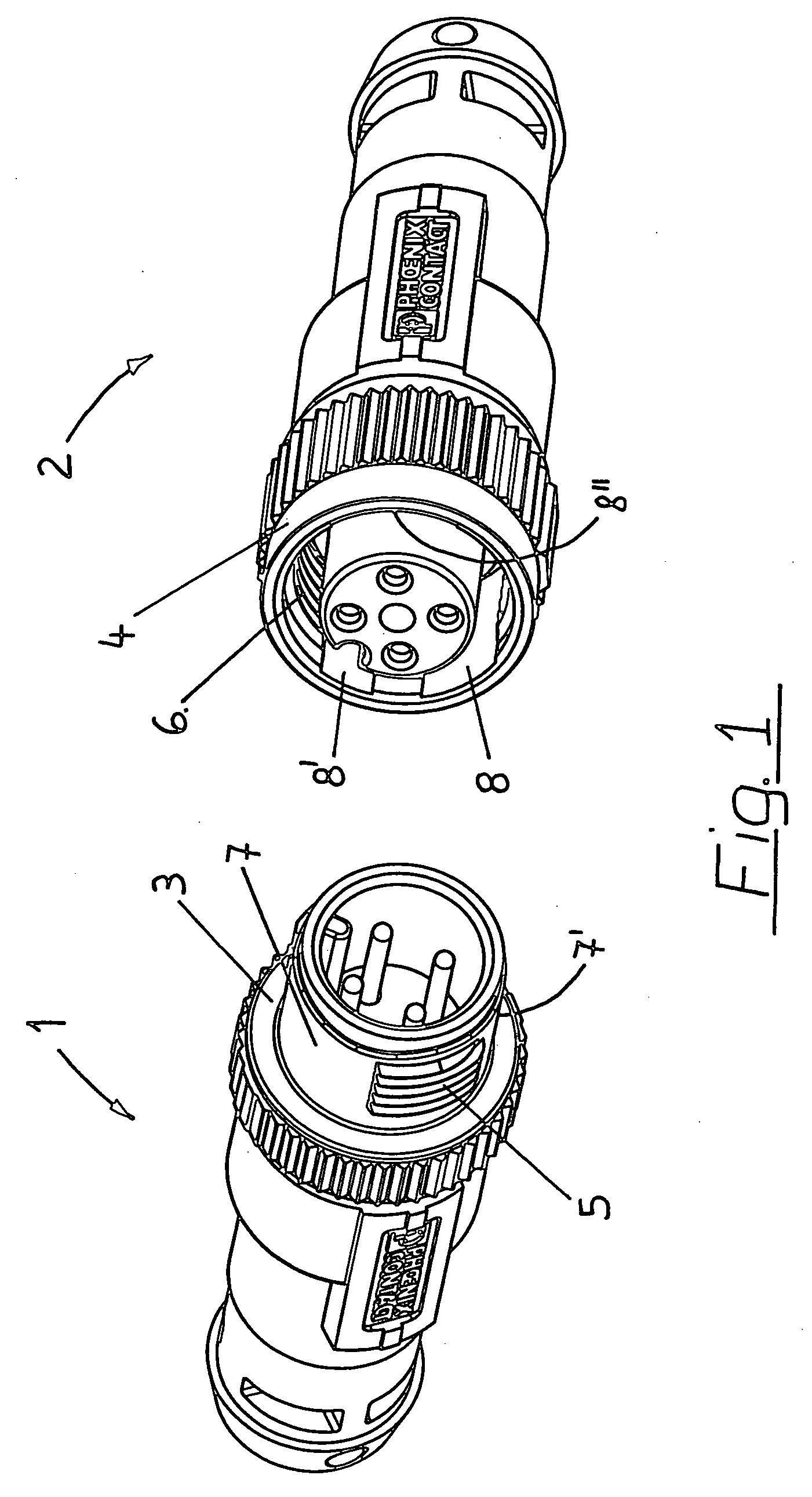
[0021] In the overall construction of their components, connectors 1, 2 according to FIG. 1 are distinguishable from commercially available connectors, for sensor connections or valve connections for example, by the use of novel screw connections in the form of a threaded sleeve 3 and a union nut 4. In their external outline, threaded joint components 3 and 4 are compatible with the commercially available connectors of this type. The compatibility enables commercially available connectors and connectors 1, 2 according to FIG. 1 having the features for quick connection to be combined without disadvantage.

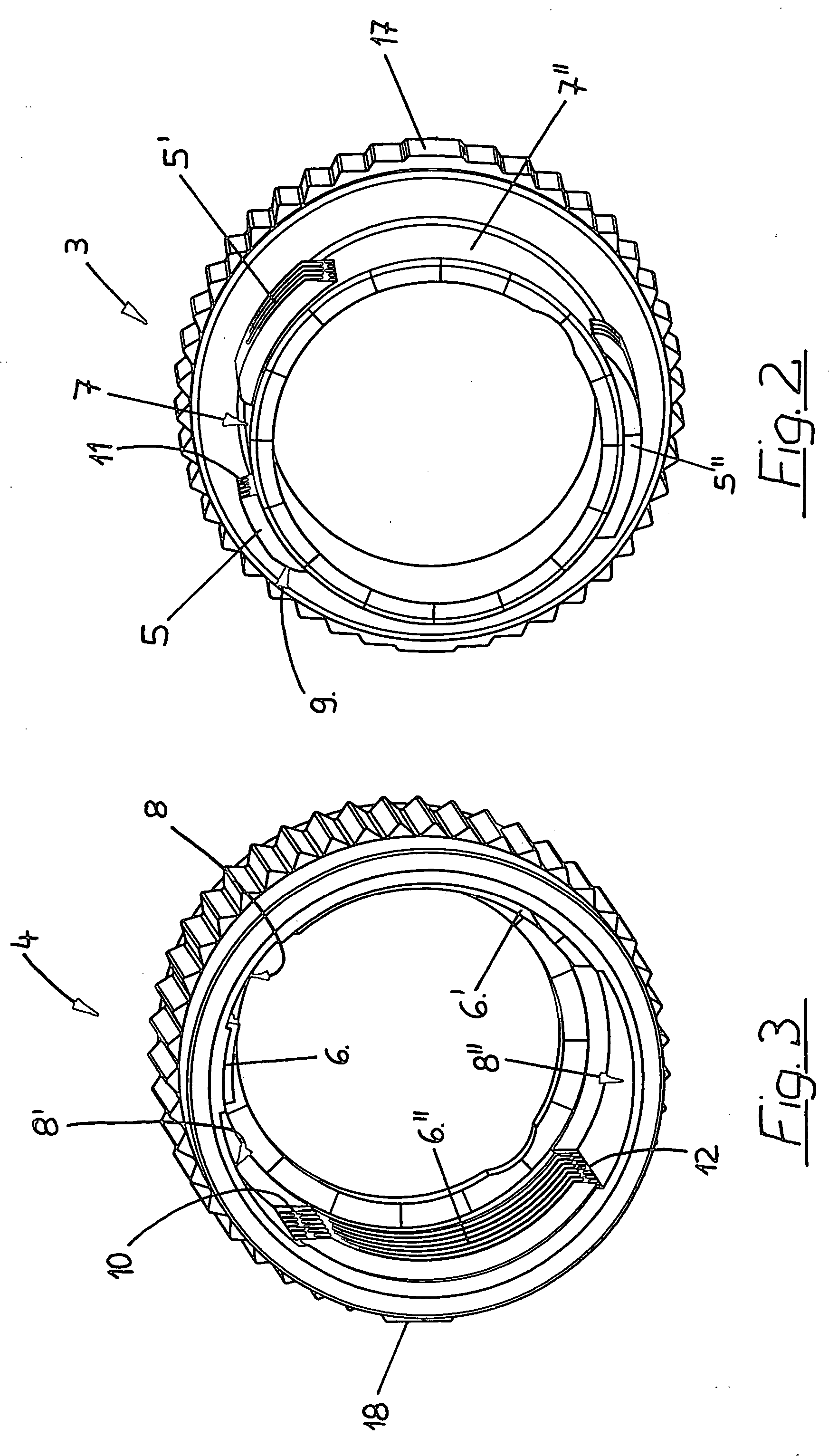
[0022] An external thread is provided on threaded sleeve 3 according to FIG. 1, which exists, however, only in some areas 5 of the circumference of threaded sleeve 3. Positioning of these threaded areas 5 creates threadless areas 7, 7′ which may receive an internal threaded area 6 of a union nut. In contrast, socket 2 has a union nut 4 including an internal thread 6 which has thread...


PUM


Abstract

An electrical connector includes an electrical plug having a threaded sleeve for screwing on a union nut of an electrical socket or for screwing into a stationary housing component of an electronic device. The threaded sleeve includes an external thread not having a threadless area. The union nut includes an internal thread configured for threaded engagement with the external thread of the plug. The internal thread has at least one threadless area.

Description

[0001] This is a continuation of application Ser. No. 10 / 725,797, filed Dec. 2, 2003, the entire subject matter of which is hereby incorporated by reference herein.[0002] The present invention relates to an electrical connector having a plug connector which is designed as a threaded sleeve for screwing on a union nut of a socket connector which is connectable to the plug. BACKGROUND [0003] It is known in connectors to protect the plug and socket against unintentional separation by using a union nut. In order to prevent the screwed connection from disengaging, the union nut is usually screwed onto the corresponding external thread of the plug up to an axial stop, which is frequently axially sealed by an O-ring seal or the like, and tightened. If, in the event of damage, the plug and socket connection must be disengaged quickly and a damaged part must be replaced, the time required for engaging and disengaging such a plug and socket connection is a disadvantage in these known connecto...

Claims


Application Information

Patent Timeline
IPC IPC(8): H01R4/38H01R13/622
CPCH01R13/622
Inventor STARKE, CORDREIMCHEN, VALERIBECKER, MARKUS
Owner PHOENIX CONTACT GMBH & CO KG
Why Eureka
Try Eureka