Outsole

a technology of outsoles and rubber soles, applied in the field of outsoles, can solve the problems of affecting the stability of runners, floating effect, and insufficient yield, and achieve the effect of softness, resilience, and simple design

Inactive Publication Date: 2005-11-17
GLIDEN LOCK
View PDF4 Cites 52 Cited by
  • Summary
  • Abstract
  • Description
  • Claims
  • Application Information

AI Technical Summary

Benefits of technology

[0008] This not only results in a sufficient shock absorption if the runner's foot contacts the ground obliquely and / or with a slight propulsive force, but also in a superior stability at the respective point of impact or load application, from which the runner is able to directly push off again without any loss in distance. The previously described floating effect is prevented in this fashion.
[0010] According to one preferred embodiment of the invention, the critical point of deformation is only reached after a tangential and / or perpendicular deformation path that is greater than 20% of the deformable thickness of the sole, if applicable, even greater than 50% of this thickness. The absolute deformation value may easily reach a few cm.

Problems solved by technology

However, these outsoles are relatively rigid in the horizontal or tangential direction and do not yield sufficiently if the runner's foot contacts the ground obliquely and with a slight propulsive force.
This rigidity in the horizontal or tangential direction is required because a more significant deformability of the sole in the horizontal direction would inevitably result in a floating effect.
This would negatively influence the stability of the runner.
In addition, the runner would lose at least a certain distance with each step because the sole would initially have to slightly deform in the respectively opposite direction when the runner pushes off in the running direction.

Method used


Image

  • Outsole
  • Outsole
  • Outsole

Examples


Embodiment Construction

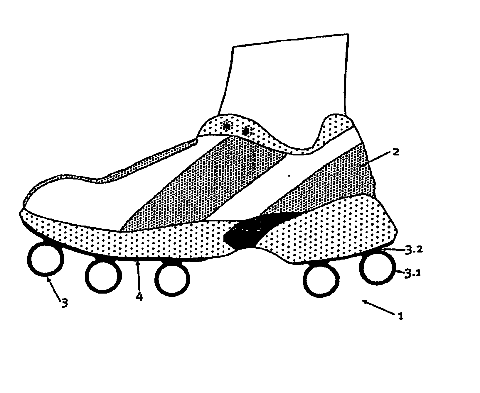
[0025] One embodiment of the invention is initially described below with reference to FIG. 1. Although this embodiment does not necessarily represent the most preferred embodiment of the invention, it suffices for explaining the essential characteristics of the invention.

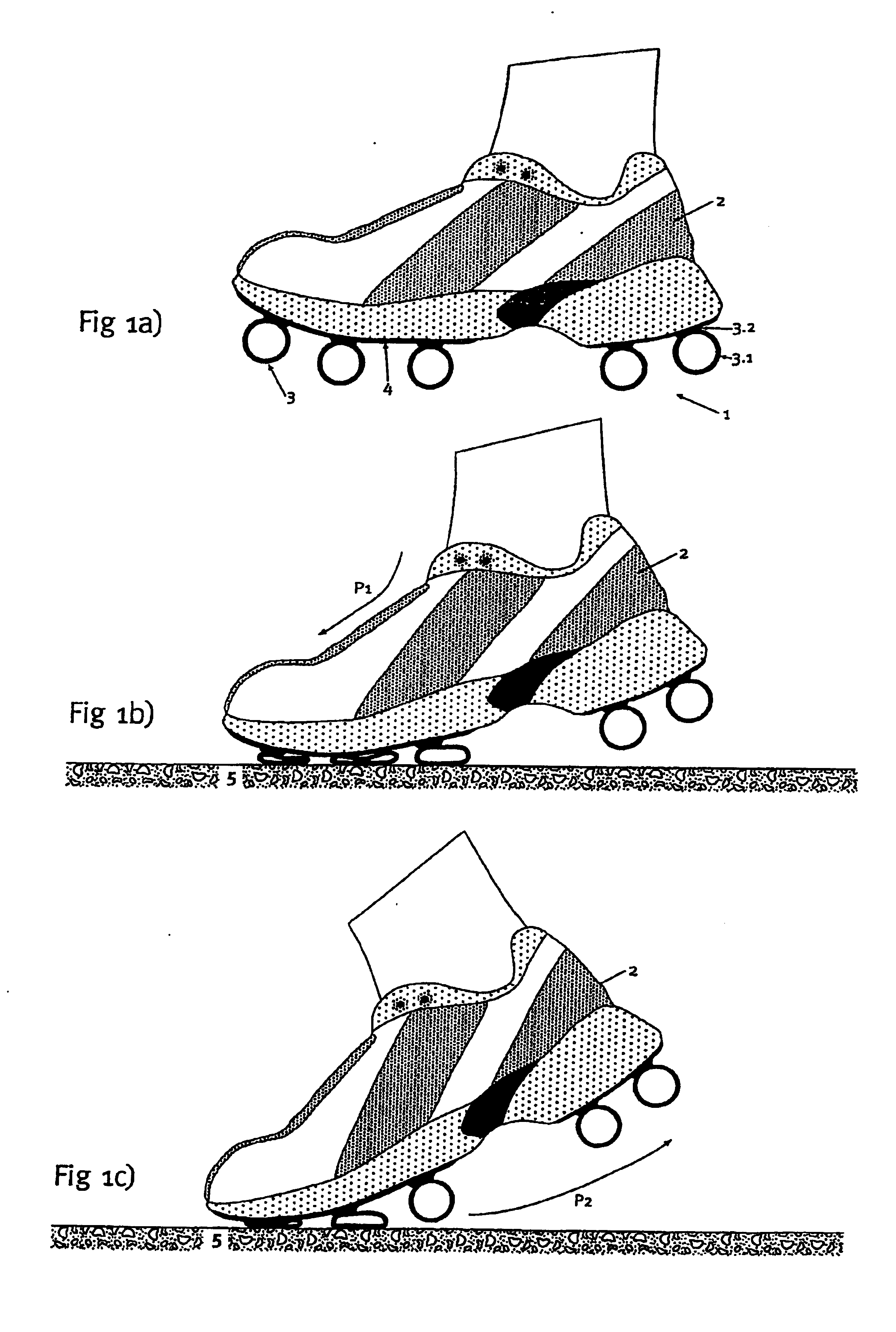
[0026]FIG. 1 shows a running shoe 2 that is equipped with an outsole 1 according to the invention. The outsole 1 is formed by a plurality of profile-like hollow elements 3 that contain tubular parts 3.1 and are fixed to the underside of an intermediate sole 4 of the running shoe 1 with webs 3.2 that are integrally formed thereon, e.g., by means of bonding. The hollow elements 3 are, for example, manufactured from a rubber material that is able to at least partially deform in an elastic fashion under the loads that occur while running. The material preferably has a high static friction with respect to other materials, but also with respect to itself. Several hollow elements 3 are arranged behind one another in the l...


PUM


Abstract

An outsole (1, 3), in particular, for athletic shoes (2) can be realized with a significant elastic deformability in the tangential direction so as to also achieve a superior shock-absorption when the foot contacts the ground obliquely and with a slight propulsive force. According to the invention, the sole (1) essentially is only rigid to a tangential deformation beyond at least one critical point of deformation in the region that is deformed to this critical point. This results in a correspondingly increased stability for the runner in the respective point of contact or load application. The runner is also able to push off from the point of load application without any loss in distance. A floating effect on the sole is prevented. The sole can be affixed, as a whole or in a plurality of parts, also detachably to an intermediate sole (4) of the shoe (2).

Description

TECHNICAL FIELD [0001] The present invention pertains to an outsole, in particular, for athletic shoes which can also be elastically deformed in the tangential direction. [0002] In this context, the term deformation in the tangential direction refers to a deformation in the direction tangential or parallel to the plane of the outsole or its outer surface which, for example, is caused by shearing. Such a deformation differs from a deformation in the direction perpendicular to the plane of the outsole or its outer surface which, for example, is caused by compression. On a horizontal surface, the tangential direction approximately coincides with the horizontal direction, and the perpendicular direction approximately coincides with the vertical direction. STATE OF THE ART [0003] Outsoles with elastically resilient outsoles are known in numerous variations, wherein different elastic materials of various hardnesses are used. There also exist outsoles with embedded air or gel cushions. The...

Claims


Application Information

Patent Timeline
Patent Type & Authority Applications(United States)
IPC IPC(8): A43B13/14A43B3/24A43B5/06A43B13/18A43B13/20A43B13/36A63B25/10
CPCA43B3/24A43B3/246A43B13/184A63B25/10A43B13/206A43B13/36A43B13/203
Inventor BRAUNSCHWEILER, H G
Owner GLIDEN LOCK
Why Eureka
Try Eureka