Video signal receiving apparatus and method

Inactive Publication Date: 2005-11-24
KK TOSHIBA
View PDF7 Cites 43 Cited by
  • Summary
  • Abstract
  • Description
  • Claims
  • Application Information

AI Technical Summary

Benefits of technology

[0013] a control section configured to change t

Problems solved by technology

However, the foregoing Publication has no di

Method used


Image

  • Video signal receiving apparatus and method
  • Video signal receiving apparatus and method
  • Video signal receiving apparatus and method

Examples


Embodiment Construction

[0022] One embodiment of the present invention will be described below with reference to the accompanying drawings.

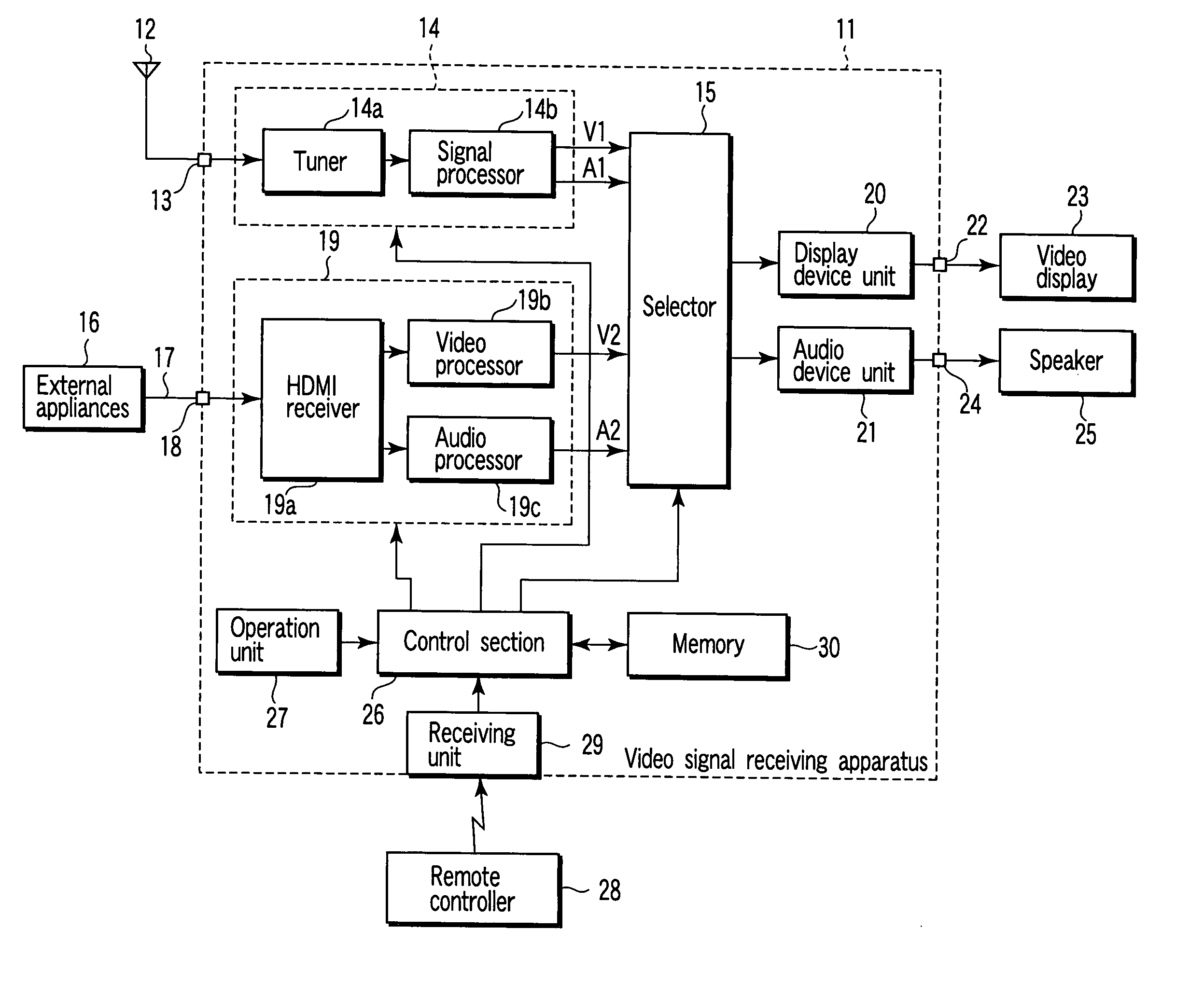
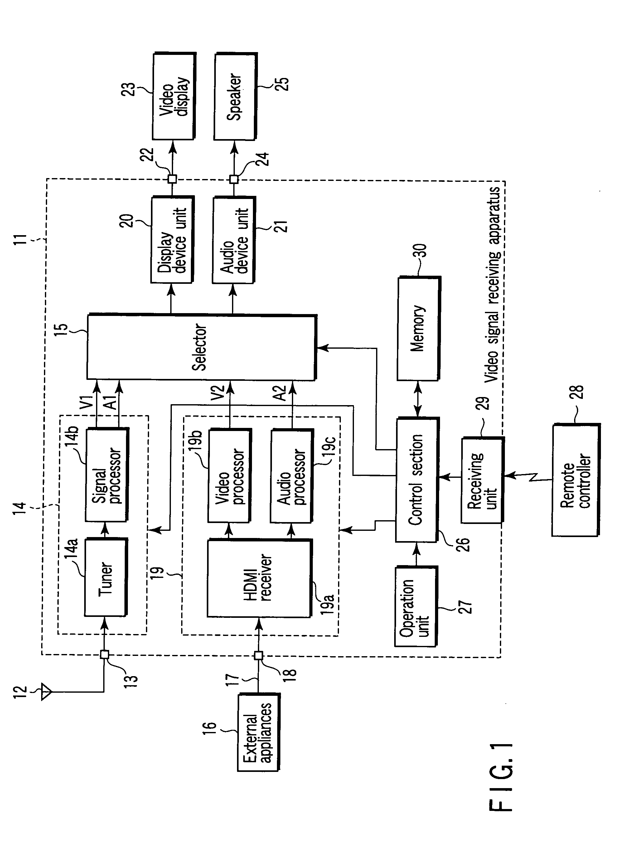
[0023]FIG. 1 shows a video signal receiving apparatus 11 explained in this embodiment. The video signal receiving apparatus 11 has the functions given below. One is a function of receiving a television broadcast signal, and another is a function of receiving a digital video signal conformable to the HDMI standards.

[0024] More specifically, a television broadcast signal is received by an antenna 12, and then, supplied to a television signal processing section 14 via a TV (television) input terminal 13. The television signal processing section 14 has tuner 14a and signal processor 14b.

[0025] The television broadcast signal inputted to the TV input terminal 13 is supplied to the tuner 14a so that a predetermined channel signal is extracted. Thereafter, an output signal of the tuner 14a is supplied to the signal processor 14b, and then, restored to analog video signal V1...


PUM


Abstract

A video signal receiving apparatus comprises a HDMI receiver, signal processing section and control section. The HDMI receiver separates a digital signal conformable to HDMI standards into video component and audio component, determining whether a received digital video signal is a RGB or YCbCr signal, and changing its setting in accordance with the determination result. The signal processing section decodes video signal and audio signal separated by the HDMI receiver to restore analog video signal and audio signal. The control section changes the setting of the HDMI receiver by an operation.

Description

CROSS-REFERENCE TO RELATED APPLICATIONS [0001] This application is based upon and claims the benefit of priority from prior Japanese Patent Application No. 2004-150642, filed May 20, 2004, the entire contents of which are incorporated herein by reference. BACKGROUND OF THE INVENTION [0002] 1. Field of the Invention [0003] The present invention relates to a standardized digital transmission system, which transmits a digital video signal having a digital audio signal multiplexed for a predetermined period. In particular, the present invention relates to video signal receiving apparatus and method for receiving a transmitted digital video signal. [0004] 2. Description of the Related Art [0005] As is well known, the DVI (Digital Visual Interface) standards have come to wide use as the standards for transmitting a digital video signal. Recently, the HDMI (High Definition Multimedia Interface) standards have been employed as the standards of further improving the DVI standards. [0006] The...

Claims


Application Information

Patent Timeline
IPC IPC(8): H04N5/268H04N5/44H04N5/46H04N7/04H04N7/045H04N7/08H04N7/081H04N9/00H04N9/64
CPCH04N5/4401H04N9/641H04N9/642H04N21/4854H04N21/4348H04N21/43635H04N21/4318H04N21/426
Inventor WATANABE, KIYOMI
Owner KK TOSHIBA
Why Eureka
Try Eureka