Image forming apparatus with predetermined copy quality set by user or operator

Active Publication Date: 2007-01-23
KK TOSHIBA +1
View PDF11 Cites 2 Cited by
  • Summary
  • Abstract
  • Description
  • Claims
  • Application Information

AI Technical Summary

Benefits of technology

[0008]An object of the present invention to reflect precisely a user's demand by outputting a warning so as to change setting o

Problems solved by technology

As the result, the copy speed becomes low.
If the compression is performed with a high compression rate, the image quality is deteriorated, but the copy speed is increased.
Therefore, a user's demand cannot be reflected precisely.

Method used


Image

  • Image forming apparatus with predetermined copy quality set by user or operator
  • Image forming apparatus with predetermined copy quality set by user or operator
  • Image forming apparatus with predetermined copy quality set by user or operator

Examples


Embodiment Construction

[0016]Hereinafter, an image forming apparatus according to an embodiment of the present invention will be described with reference to the drawings.

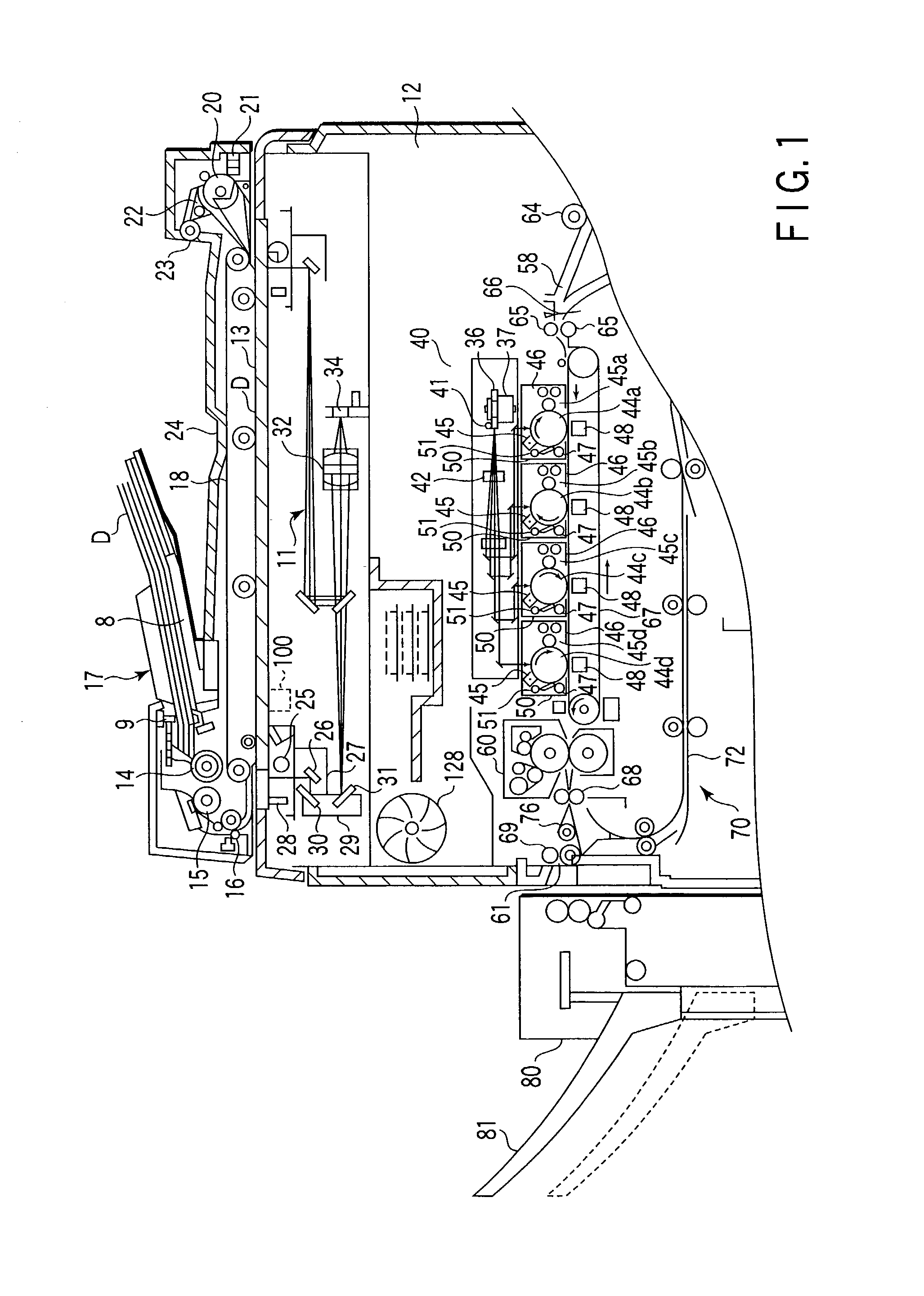
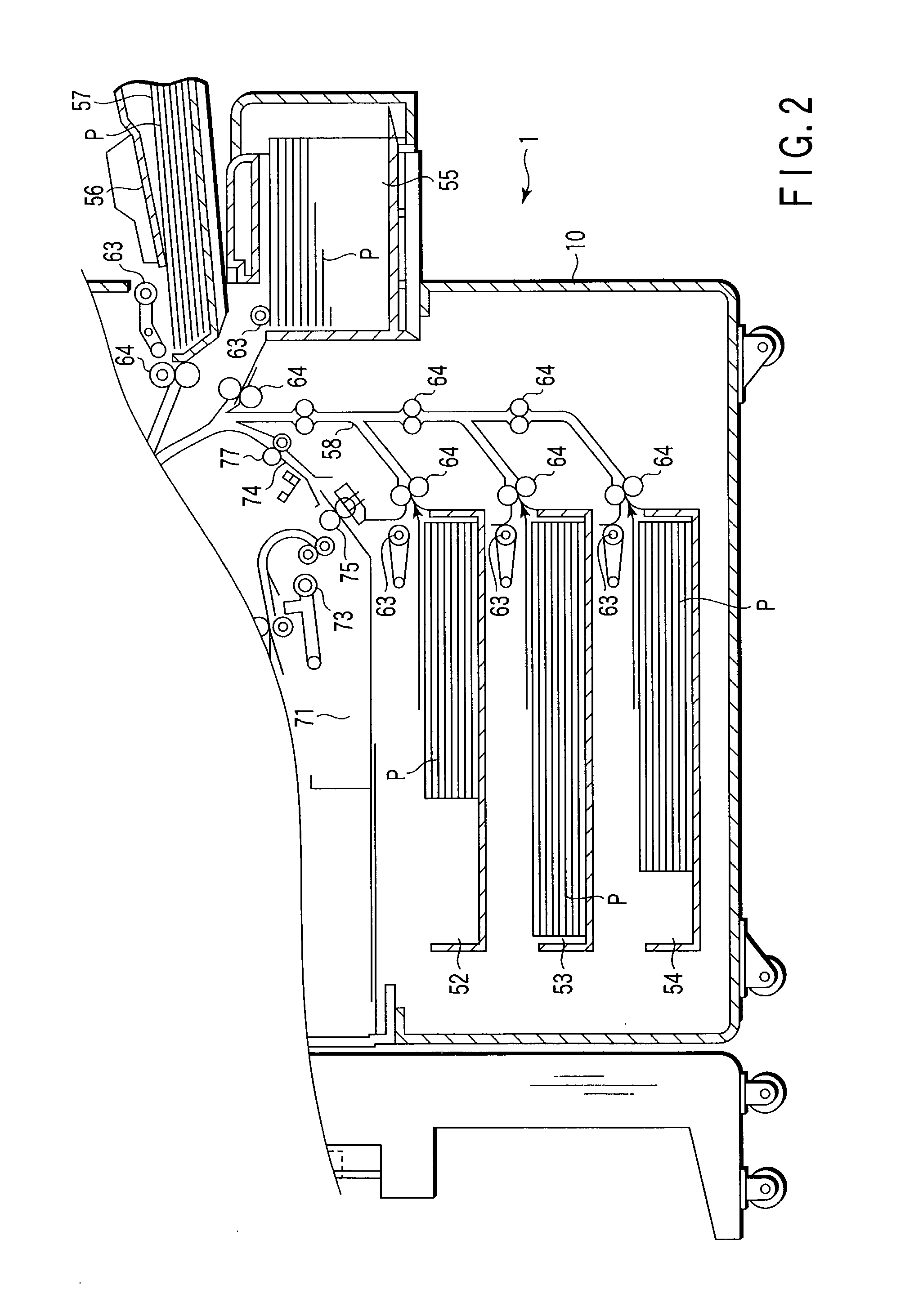
[0017]FIGS. 1 and 2 are cross-sectional views showing a schematic structure of a color digital copying machine 1 which is an example of the image forming apparatus of the present invention.

[0018]As shown in FIGS. 1 and 2, the digital copying machine 1 comprises a main body 10. A scanner section 11 serving as reading means and a color printer section 12 which functions as image forming means are provided within the main body 10.

[0019]An automatic document feeder (hereinafter referred to as ADF) 17 which serves as a document cover and automatically feeds sheet-like documents one-by-one is provided at an upper portion of the main body 10 so as to be opened and closed. In place of the ADF 17, a platen may be mounted to the upper portion of the main body 10 as the document cover. An operation panel (not shown) including various types of operat...


PUM


Abstract

The present invention can reflect precisely a user's demand by outputting a warning so as to change setting of a compression method and a compression rate when sufficient image quality cannot be obtained with a currently set compression rate in color copying.

Description

BACKGROUND OF THE INVENTION[0001]The present invention relates to an image forming apparatus such as a full color copying machine or a color printer.[0002]A so-called 4-series-tandem type full color copying machine has been conventionally known as an image forming apparatus which outputs a color image. In a four-tandem full color copying machine, four image forming units which respectively form yellow (Y), magenta (M), cyan (C) and black (BK) toner images on the basis of a color-separated image signal are disposed along a conveying belt.[0003]Each color image forming unit includes a photo-sensitive drum which rotatably contacts a conveying belt, a charging device which charges a drum surface to a predetermined potential, an exposure device which exposes the drum surface with light to form an electrostatic latent image, a development device which supplies toner to the electrostatic latent image on the drum surface to develop the electrostatic latent image, and a transfer device which...

Claims


Application Information

Patent Timeline
IPC IPC(8): B41B25/00G06T9/00H04N1/333
CPCG06T9/00H04N1/0048H04N1/33307H04N2201/33357H04N2201/0081H04N2201/0082
Inventor IWASAKI, TAKAO
Owner KK TOSHIBA
Why Eureka
Try Eureka