System and method for implementing multiple spanning trees per network

Active Publication Date: 2005-11-24
CISCO TECH INC
View PDF75 Cites 48 Cited by
  • Summary
  • Abstract
  • Description
  • Claims
  • Application Information

AI Technical Summary

Benefits of technology

[0007] In some embodiments, a method involves operating several virtual network device sub-units as a single virtual network device and preventing a packet from being sent to one of the virtual network device sub-units, if that one of the virtual network device sub-units has already received the packet. Operating the virtual network device sub-units as a single virtual network device involves communicating control information from one of the virtual network device sub-units to one or more other ones of the virtual network device sub-units via one or more virtual network device links.
[0008] In other embodiments, a method involves: receiving a packet via a first interface of a first one of several virtual network device sub-units of a virtual network device and associating the packet with the first one of the virtual network device sub-units. The method also invol

Problems solved by technology

However, if multiple redundant links are active at the same time, management of those links may be undesirably complicated (e.g., due to the need to avoid bridging loops).
This complexity extends to other situations in which multiple redundant components are used during normal operation.
For example, if multiple redundant routers are simultaneously used in a network, management of the network may become more complicated due to the need to have a different point of management for each network device.

Method used


Image

  • System and method for implementing multiple spanning trees per network
  • System and method for implementing multiple spanning trees per network
  • System and method for implementing multiple spanning trees per network

Examples


Embodiment Construction

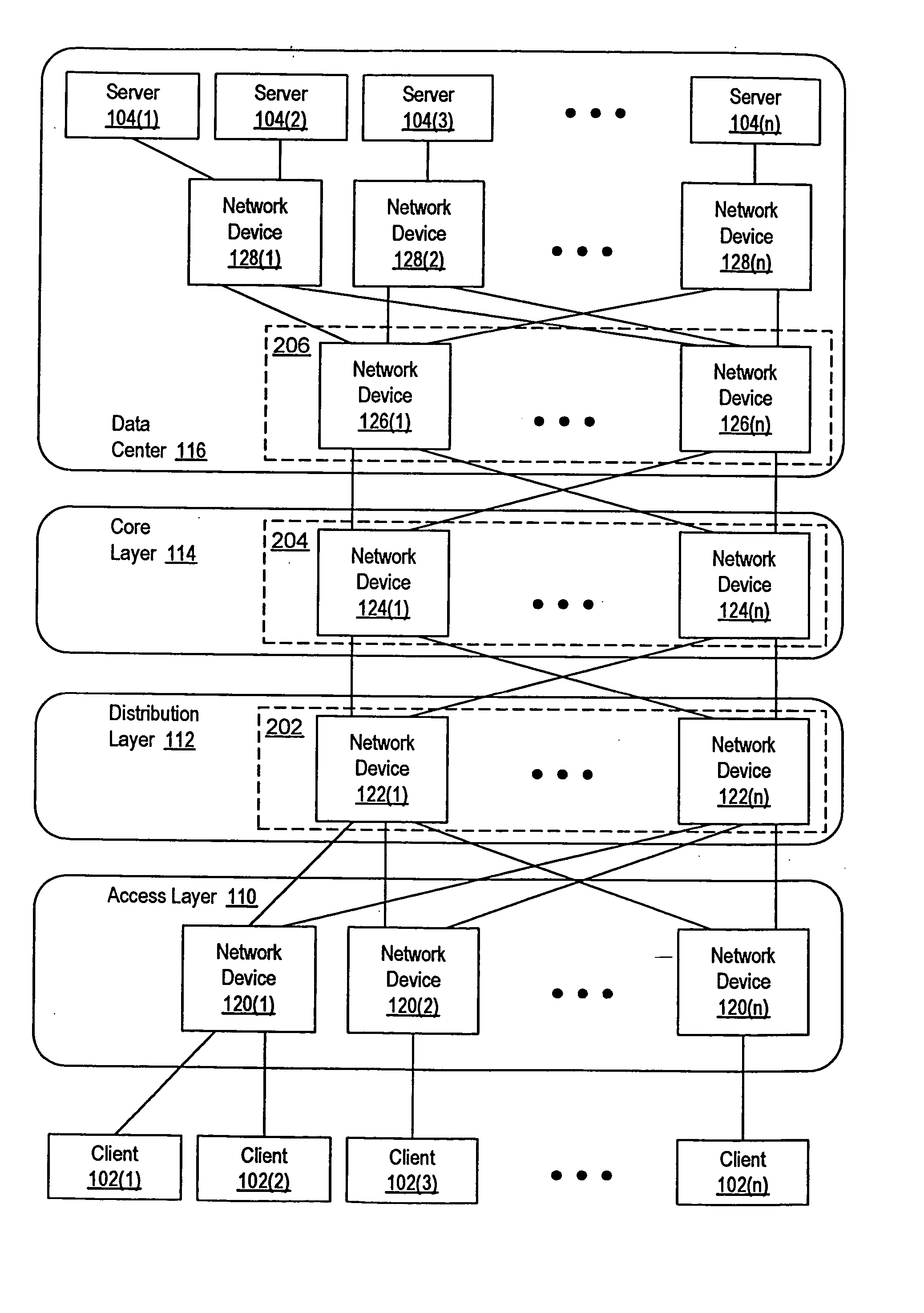
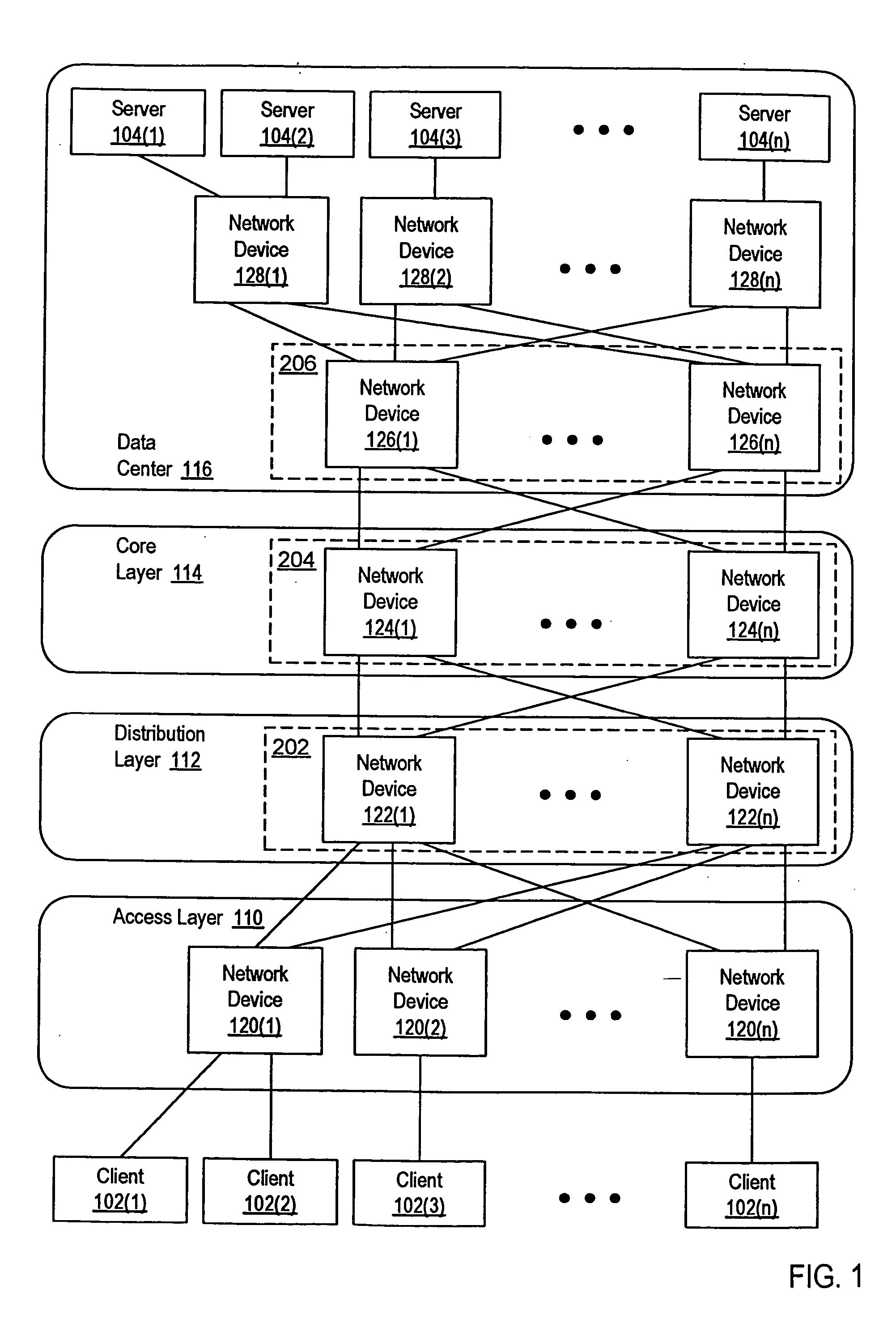
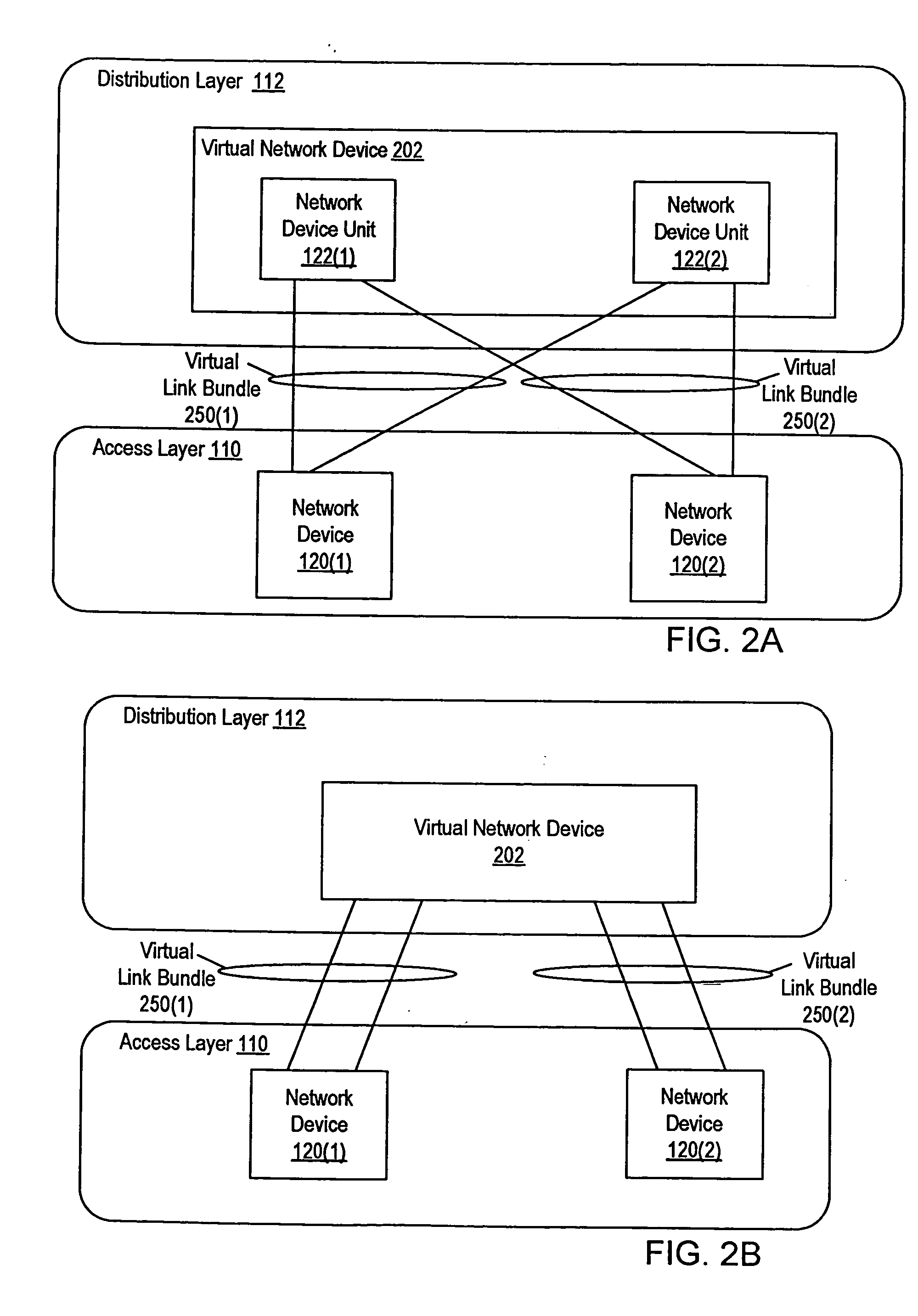
[0030] Virtual network device cluster are formed from two or more virtual network device sub-units, which collectively operate as a single logical device. FIGS. 1-3 provide an example of an environment that can include one or more virtual network devices. FIGS. 4-7 provide examples of virtual network device clusters and the operation of virtual network device clusters. FIGS. 8A-9C illustrate how several ingress-specific spanning trees can be used to control how packets are forwarded through a virtual network device cluster. FIGS. 10A-11B illustrate how multiple ingress-specific spanning trees can also be used to control how packets are forwarded in other types of networks.

[0031]FIG. 1 is a block diagram of a network that includes several virtual network devices. In FIG. 1, several clients 102(1)-102(n) communicate with each other and with several servers 104(1)-104(n) via a network. Clients 102(1)-102(n) can include a variety of different devices that access networked services. For...


PUM


Abstract

A virtual network device cluster includes several different virtual network device sub-units, which collectively operate as a single logical network device. The virtual network device cluster identifies the virtual network device sub-unit via which a given packet enters the virtual network device cluster. A packet is forwarded through the virtual network device cluster based on which virtual network device sub-unit has been identified for that packet. In one embodiment, a method involves receiving a packet via a first interface of a first one of several virtual network device sub-units of a virtual network device and associating the packet with the first one of the virtual network device sub-units. The method also involves inhibiting the packet from being sent via an interface of one of the virtual network device sub-units, in response to the packet being associated with the first one of the virtual network device sub-units.

Description

BACKGROUND OF THE INVENTION [0001] 1. Field of the Invention [0002] The present invention relates to networking and, more specifically, to virtual network devices. [0003] 2. Description of the Related Art [0004] In order to provide increased network reliability, redundant switches and links are often included in a network. If a switch or link fails, a redundant switch or link, already in place within the network, can quickly be enabled to replace the failed switch or link. Since the redundant switch or link can typically be enabled as a replacement more quickly than the failed component can be replaced or repaired, having redundant links and / or switching provides a more reliable network. [0005] When redundant components are included within a network, it is often desirable to be able to use the redundant components during normal network operation, before the failure of corresponding components. For example, if two links are implemented between a pair of switches, it is desirable to u...

Claims


Application Information

Patent Timeline
IPC IPC(8): H04L45/586H04L12/46H04L12/56H04L45/18
CPCH04L12/4625H04L45/02H04L45/586H04L45/24H04L45/18
Inventor SMITH, MICHAEL R.
Owner CISCO TECH INC
Why Eureka
Try Eureka