Stand-alone microphone test system for a hearing device

a technology for hearing aids and test systems, applied in hearing aid testing/monitoring, hearing device specific tools, electric devices, etc., can solve problems such as microphone deformation, microphone deformation, microphone deformation by a significant amount, and/or inadequate methods and apparatus used to test the quality of the microphon

Inactive Publication Date: 2005-11-24
COCHLEAR LIMITED
View PDF10 Cites 38 Cited by
  • Summary
  • Abstract
  • Description
  • Claims
  • Application Information

AI Technical Summary

Benefits of technology

[0009] According to a second aspect of the present invention, there is provided a stand-alone microphone test system for a hearing device, said test system including a test device having a housing adapted to receive a hearing device having at least one microphone, and a sound source operatively adapted to communicate with the hearing device, said housing operatively maintaining the sound source and said or each microphone in a predetermined relationship, said hearing device further including a comparator and means for generating a test signal for transmission to said sound source, so that operatively, when the sound source receives a test signal from the hearing device, it produces an acoustic signal which is received by said or each microphone, said microphone detecting said signal and communicating a corresponding received signal to said comparator, said hearing device further sending a reference signal to said comparator, so that said received signal and said reference signal can be compared to determine the quality of the or each microphone.

Problems solved by technology

The available methods and apparatus used to test the quality of the microphone are inadequate, expensive, and / or prone to error or uncertainty.
First, a microphone may degrade due to natural degradation over time.
Second, a microphone may degrade by a significant and / or sudden failure, not caused by natural degradation.
This requires time and effort as a complete speech test should be conducted in a reproducible environment.
Typically, an effective technical measurement technique for measuring the frequency response of a microphone is to utilize specialized and expensive analysis equipment.

Method used


Image

  • Stand-alone microphone test system for a hearing device
  • Stand-alone microphone test system for a hearing device
  • Stand-alone microphone test system for a hearing device

Examples


Embodiment Construction

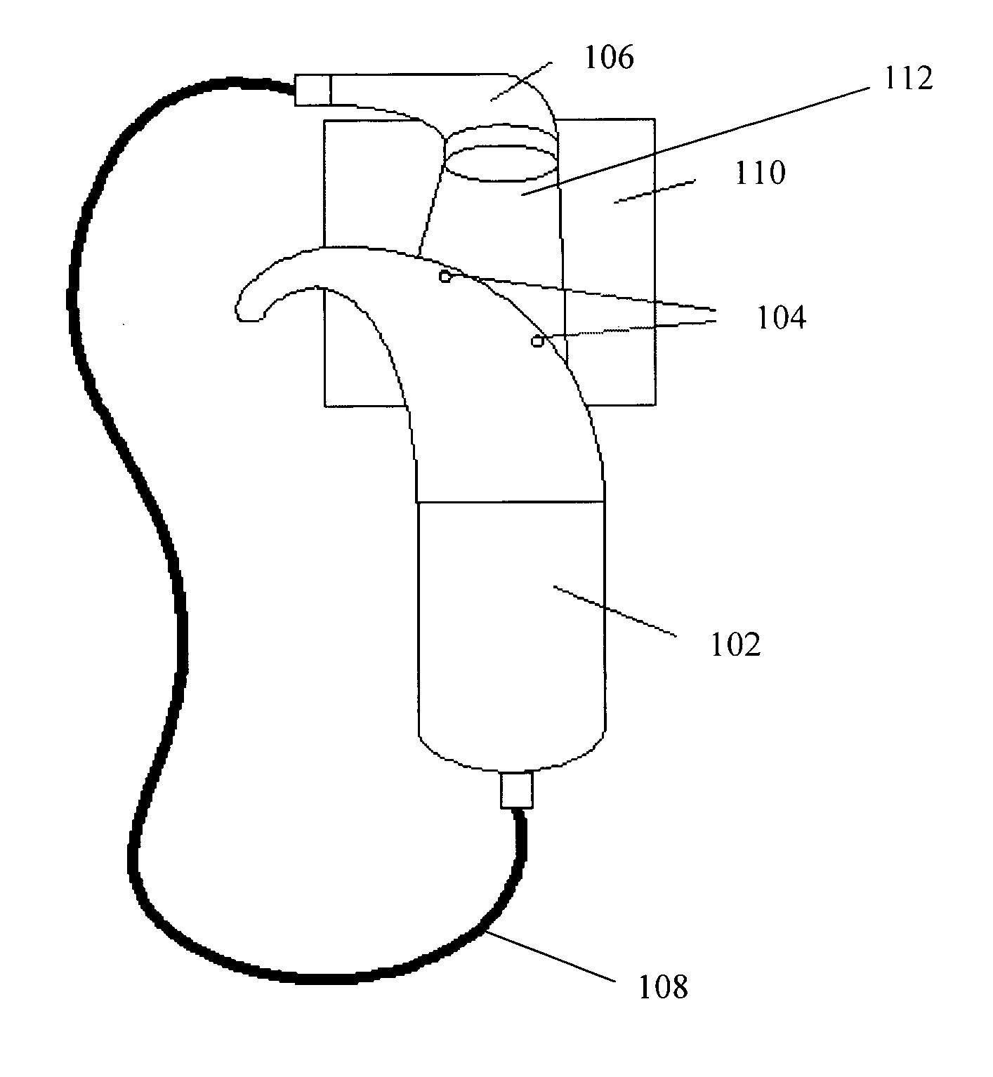
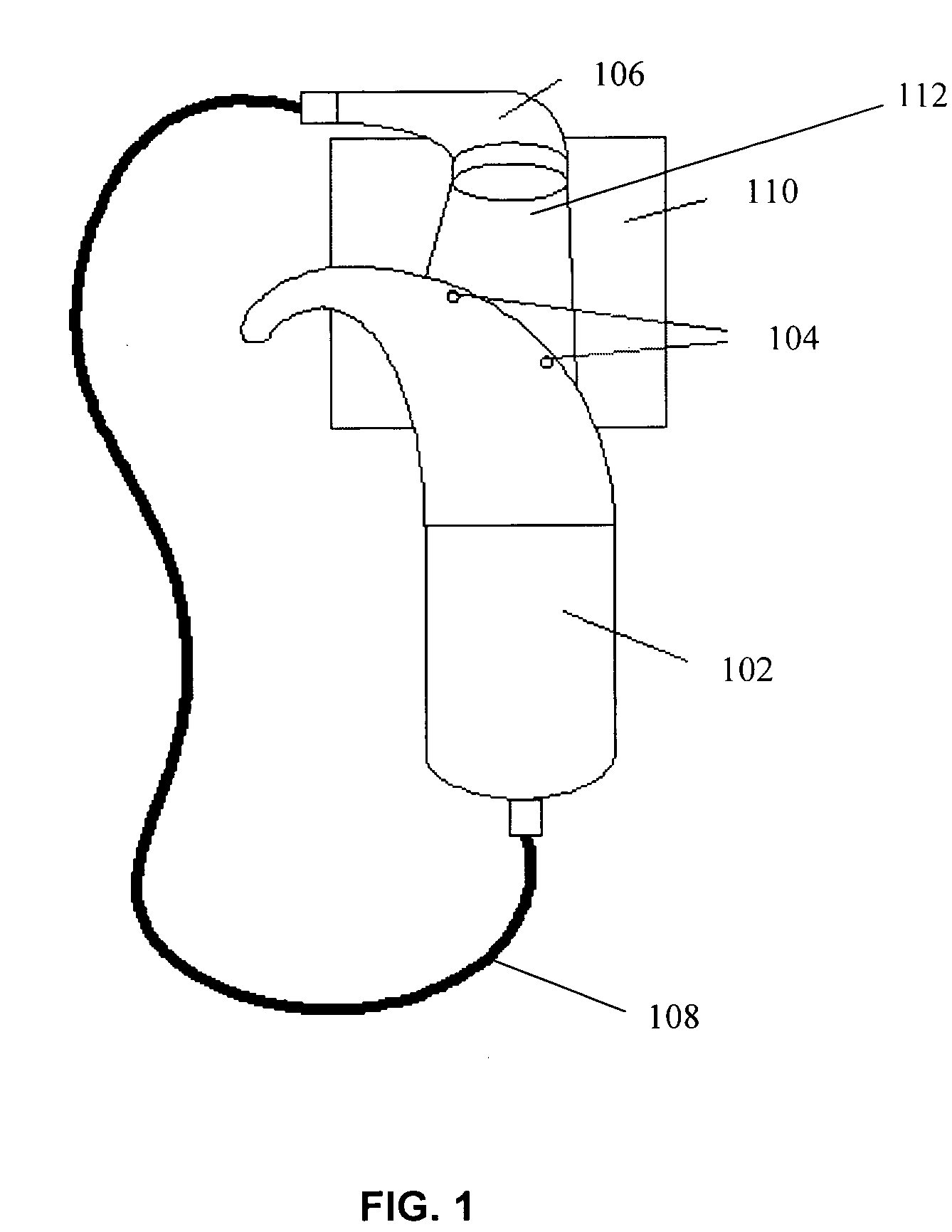
[0024] An exemplary embodiment of the present invention provides a stand-alone microphone test device and method that is easy to use and economical. The stand-alone test may be used by patients who wear a hearing device and other non-medical personnel without extensive training or expertise.

[0025] In some current systems, a user may be provided with an indication on an LED or LCD that there is sound being produced, but the internal diagnostics are inadequate to determine the quality of the microphone. A technician or other individual may listen to an attached earphone to judge the quality of the speech processor, but may not be able to determine the quality or condition of the microphone, without using an auxiliary testing system. A technician or clinician may utilize a separate commercial-off-the-shelf (COTS) microphone test system, such as a FONIX™ box, to measure the quality of a microphone.

[0026] According to an embodiment of the present invention, a user may perform a microph...


PUM


Abstract

The present invention provides a stand-alone microphone test system for a hearing device, comprising a hearing device having at least one microphone, a sound source in communication with the hearing device, wherein, when in operation, the sound source receives a signal from the hearing device, and a mold oriented to hold the hearing device and the sound source such that output from the sound source may be directed to the at least one microphone. There is also provided a stand-alone microphone test method for a hearing device, comprising providing a test signal / sequence output to a sound source / receiver, providing a reference signal to a comparator, receiving output from the Sound source / receiver in a microphone, transmitting the received signal to the comparator, comparing the received signal with the reference signal, and providing a test result.

Description

BACKGROUND [0001] 1. Field of the Invention [0002] The present invention relates generally to stand-alone microphone test devices and systems for hearing aids and hearing prostheses, and to a testing method for microphones in such devices. [0003] 2. Related Art [0004] A prosthetic hearing device or hearing aid is used to aid patients who have a hearing deficiency. Microphone quality greatly influences a patient's satisfaction and ability to discern sound. The available methods and apparatus used to test the quality of the microphone are inadequate, expensive, and / or prone to error or uncertainty. [0005] Microphones degrade in two primary ways. First, a microphone may degrade due to natural degradation over time. Second, a microphone may degrade by a significant and / or sudden failure, not caused by natural degradation. [0006] One typical measurement technique for measuring the frequency response of a microphone is the speech and / or sound perception of the user. This requires time and...

Claims


Application Information

Patent Timeline
Patent Type & Authority Applications(United States)
IPC IPC(8): H04R25/00H04R29/00
CPCH04R25/30H04R2460/17H04R29/004H04R25/556
Inventor VAN DEN HEUVEL, KOENGOOREVICH, MICHAEL
Owner COCHLEAR LIMITED
Why Eureka
Try Eureka