Determining device and determining method

Active Publication Date: 2017-11-30
CHEM GROUTING
View PDF0 Cites 2 Cited by
  • Summary
  • Abstract
  • Description
  • Claims
  • Application Information

AI Technical Summary

Benefits of technology

[0029]According to the present invention, since the jet nozzle (N) with the long ground penetrating (cutting) distance used in the large diameter jet grouting method is inspected by using the pressure sensing unit (2) and the controlling device (10), digital data corresponding to a pressure distribution, when the jet stream (J) impacts the pressure sensing unit (2), can be saved (registered) and the quality (of the nozzle N) can be determined.
[0030]Consequently, as different from an inspection of the prior art in which pressure sensitive paper is used in order to determine merely whether a fixed or higher pressure has been applied, a pressure distribution per unit time or per frame can be observed when the jet stream (J) impacts the pressure sensing unit (2), and it is possible to observe a fluctuation in pressure within an arbitrary numerical value range in the pressure distribution.
[0031]Additionally, according to the present invention, it is possible to obtain an area and the center coordinates of a range at which the jet stream (J) impacts the pressure sensing unit (2).
[0032]Here, in a case that an average value of pressures, which are enable to penetrate (pressures which enable to penetrate into the construction ground for a necessary distance) merely in the pressure distribution sensed by the pressure sensing unit (2) per frame, is equal to or more than a numeral value with which penetration into the construction ground is enabled for the necessary

Problems solved by technology

However, there is no technology to correctly determine whether a jet nozzle is good or defective at the stage before actually injecting a jet stream in a construction site.
However, since the pressure sensitive paper discolors when a prescribed pressure is applied thereto, it is not possible to identify a point of time at which the prescribed pressure (or a higher pressure which causes discoloration) was applied even though the p

Method used


Image

  • Determining device and determining method
  • Determining device and determining method
  • Determining device and determining method

Examples


Embodiment Construction

[0044]An embodiment according to the present invention will now be described hereinafter with reference to the accompanying drawings.

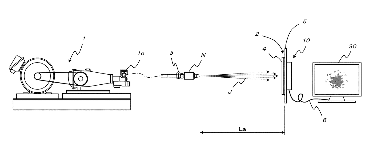
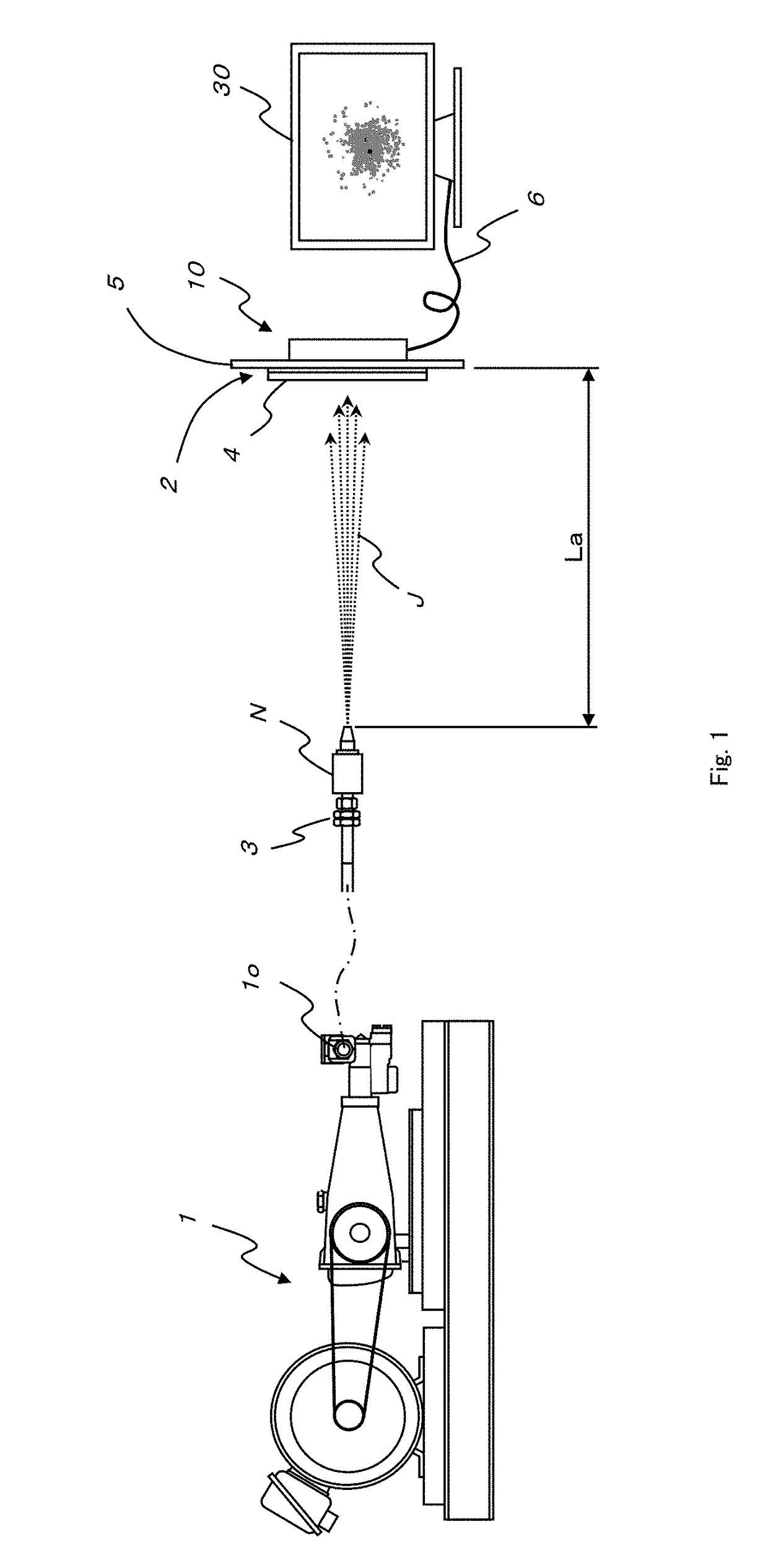
[0045]In FIG. 1, a determining device according to the embodiment of the present invention includes a jet stream generating device (a generating pump) 1, a pressure sensing unit (a pressure sensor) 2, a controlling device (a control unit) 10, and a monitor 30 as a display device.

[0046]A nozzle N as an inspection target is disposed to an attachment 3, and the attachment 3 is fixedly provided at one end (a right end in FIG. 1) of a non-illustrated pipeline. Additionally, the other end of the non-illustrated pipeline communicates with an outlet port 10 of the generating pump 1.

[0047]A front surface (a left surface in FIG. 1) of the pressure sensor 2 is covered with a protective sheet 4 as a protective member so that it is protected from impact of a high-pressure jet stream ejected from the nozzle N.

[0048]Aback surface (a right surface in FIG. 1) of the pr...


PUM


Abstract

The purpose of the present invention is to provide a determining device and a determining method to determine whether an inspected jet nozzle is defective by inspecting the jet nozzle for injecting a jet stream with long ground penetrating distance at a stage before installing in a construction site where a large diameter jet grouting method is used. To achieve this purpose, with this invention, in which a nozzle to be inspected is mounted onto an outlet port, a jet stream is ejected from a jet stream generating device, and measurement data measured by a pressure sensing unit when the jet stream impacts the pressure sensing unit is processed with a controlling device (for example, a computer), a nozzle to be inspected is determined to be a non-defective product if a first ratio is no less than a first prescribed value, a second ratio is no less than a second prescribed value, and a third ratio is no less than a third prescribed value.

Description

TECHNICAL FIELD[0001]The present invention relates to a technology inspecting a jet nozzle which is used in a large diameter jet grouting method and constructed to generate a jet stream (a jet) with a long ground penetrating distance.BACKGROUND ART[0002]As one of the means to improve soft ground, a large diameter jet grouting method for constructing a column-shaped improvement body having a large radial dimension in the ground is well-known.[0003]In this large diameter jet grouting method, it is necessary to inject a jet stream with a long distance (a ground penetrating or cutting distance) to penetrate or cut into the ground which is to be subjected to construct a column-shaped improvement body having a large radial dimension. Therefore, the quality of a jet nozzle must be maintained equal or better than a certain level. When a poor-quality jet nozzle is used, a jet stream reachable distance, i.e., the ground penetrating distance is shortened.[0004]In order to avoid a situation tha...

Claims


Application Information

Patent Timeline
IPC IPC(8): G01N7/14
CPCG01N7/14E02D3/12G01M99/008B05B15/00G01L5/0052G01M17/00
Inventor TSUCHIYA, TSUTOMUKUMEKAWA, MASANORIABE, HIROYUKI
Owner CHEM GROUTING
Why Eureka
Try Eureka