Connection structure for a watchcase with a watch chain

a technology of connecting structure and watch case, which is applied in the direction of bracelets, instruments, and horology, can solve the problems of detachment and loss of watch, inconvenient use for users, and the inability to fix the axes of the mandrel, so as to achieve the effect of convenient us

Inactive Publication Date: 2005-12-01
MODERN NATURE
View PDF6 Cites 70 Cited by
  • Summary
  • Abstract
  • Description
  • Claims
  • Application Information

AI Technical Summary

Benefits of technology

[0011] The advantage of the present invention is obvious. The watchcase can be attached with and detached from the watch chain quickly through the connection structure without any special tool. It brings more convenience to the user.
is obvious. The watchcase can be attached with and detached from the watch chain quickly through the connection structure without any special tool. It brings more convenience to the user.

Problems solved by technology

However, the detaching operation for the watchcase and the watch chain must be performed with the aid of special tools, which may bring inconvenience to the user.
If the user replaces it with own tools, unsuitable tools may risk damaging the connection structure of the watchcase and watch chain, or untight attachment between them, which may lead to detachment and losing the watch.
But the mandrels cannot be fixed in the axis direction.
Therefore, the conventional connection structure does not meet the requirement.

Method used


Image

  • Connection structure for a watchcase with a watch chain
  • Connection structure for a watchcase with a watch chain
  • Connection structure for a watchcase with a watch chain

Examples


Embodiment Construction

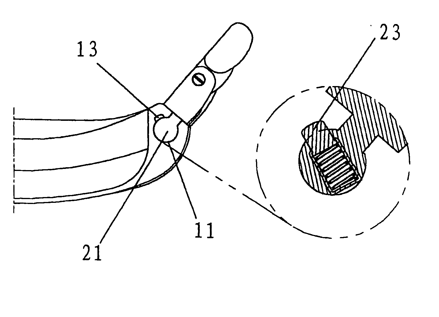
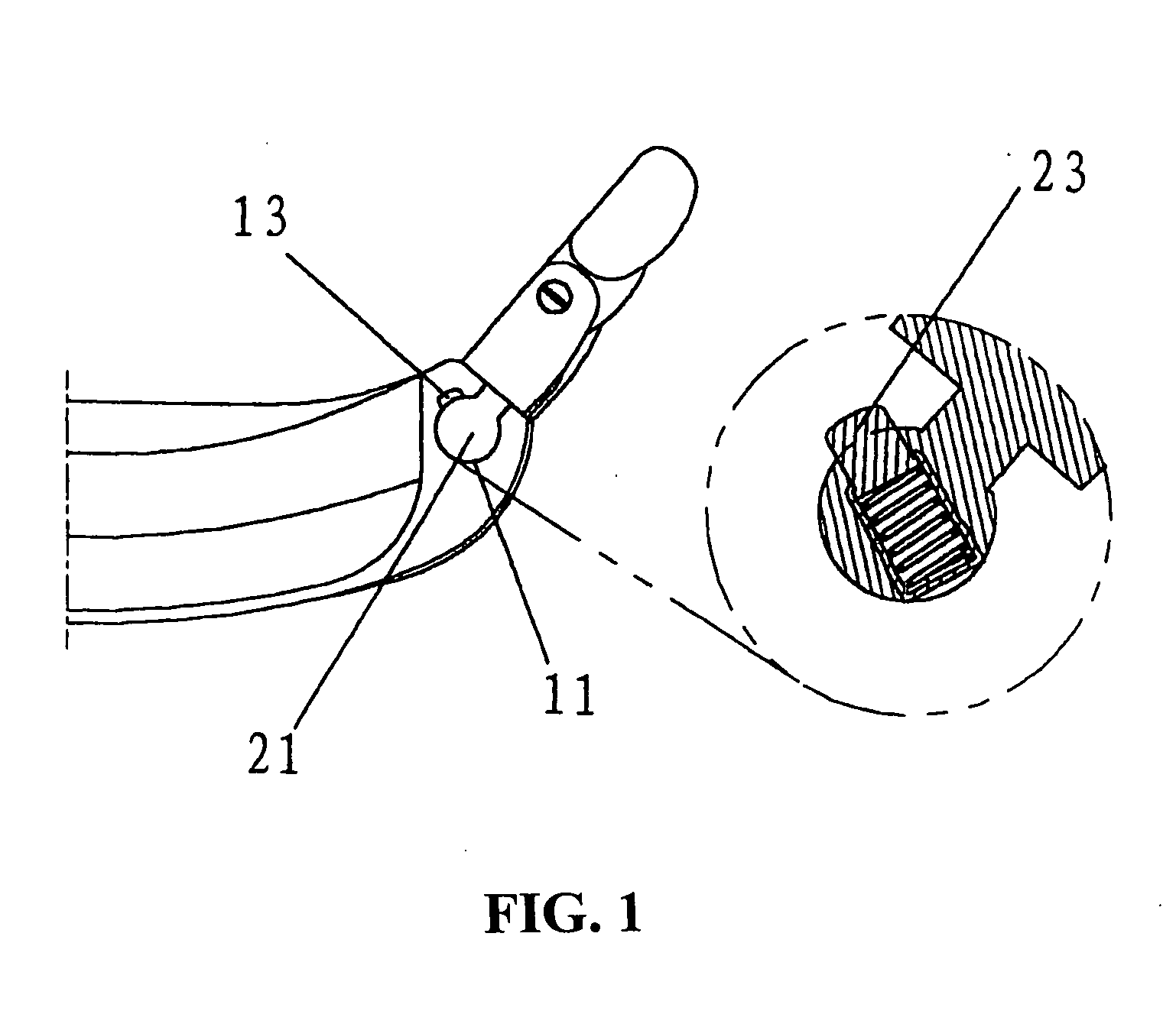
[0017] The present invention relates to a connection structure for a watchcase and a watch chain, as shown in FIGS. 1, 2 and 3. The watchcase comprises a through groove 11 on each side longitudinally and a through hole 12 vertical to a side edge of the groove 11. The watch chain comprise a flange 21 on each side engaging with the groove 11 for connecting with the watchcase, a slot 22 in the flange 21 at a position corresponding to the through hole 12, in which a locking device is provided. The locking device comprises a catapult nail 13 in the through hole 12 and an elastic element 23 in the slot 22. The watch chain and the watchcase are connected with each other by the above-mentioned connection system.

[0018] In an embodiment shown in FIGS. 1, 2 and 3, the section of the groove 12 has a half circular shape, the width between two side edges of which is smaller than the diameter of the circle. The shape of the flange of the watch chain matches with that of the groove. In use, the fl...


PUM


Abstract

A connection structure for a watchcase and a watch chain comprises a through groove on each side of the watchcase longitudinally, a through hole vertical to a side edge of the groove, a flange disposed on each side of the watch chain and engaged with the groove for connecting with the watchcase, a slot in the flange at a position corresponding to the through hole, in which a locking device is provided. The watchcase can be attached with and detached from the watch chain quickly through the connection structure without any special tool.

Description

CROSS-REFERENCE TO RELATED APPLICATION [0001] This application claims the priority benefit of Chinese Utility Model Application No. 2004200592519 filed on May 28, 2004, the content of which is hereby incorporated in its entirety herein by reference. FIELD OF THE INVENTION [0002] The present invention relates to a connection structure for a watch, particularly to a structure connecting a watchcase with a watch chain. BACKGROUND OF THE INVENTION [0003] At present, watches are widely used in our ordinary lives. A watch is becoming a necessary ornament rather than a timepiece. No one content to wear one watch during his whole life. For most people, they want to change the watch chain at will. However, the watchcase is commonly connected with the watch chain by connection bars. In such conventional construction, two pairs of lugs are disposed on both sides of the watchcase, each pair having a pair of cylindrical cavities or holes therein accommodating two ends of the bar. The connection ...

Claims


Application Information

Patent Timeline
Patent Type & Authority Applications(United States)
IPC IPC(8): G04B37/00G04B37/12G04B37/14G04B37/18
CPCG04B37/1486A44C5/14
Inventor HO, KAI CHEUNG
Owner MODERN NATURE
Why Eureka
Try Eureka