Indentation hardness test system

a test system and hardness technology, applied in the direction of material strength using tensile/compressive forces, instruments, material analysis, etc., can solve the problems of insufficient resolution and difficulty in orientation, and achieve the effect of reducing the difficulty of orientation

Active Publication Date: 2005-12-01
LECO CORPORATION
View PDF42 Cites 18 Cited by
  • Summary
  • Abstract
  • Description
  • Claims
  • Application Information

AI Technical Summary

Benefits of technology

[0011] In another embodiment, the code instructs the processor to perform the additional step of displaying an outline of the part in a composite image. The step of displaying an outline of the part in the composite image may also include the steps of: examining a frame of an image stream of the part to locate an edge of the part and moving the part in a direction parallel to the edge of the part such that the edge remains in a field of view of the camera for a next frame until the outline of the part is complete. The code may also cause the processor to perform the ad

Problems solved by technology

As briefly described above, at 5× magnification the operator has a relatively good idea of the required orientation of the “T” bar, but not enough resolution to position it within 5 microns of

Method used


Image

  • Indentation hardness test system
  • Indentation hardness test system
  • Indentation hardness test system

Examples


Embodiment Construction

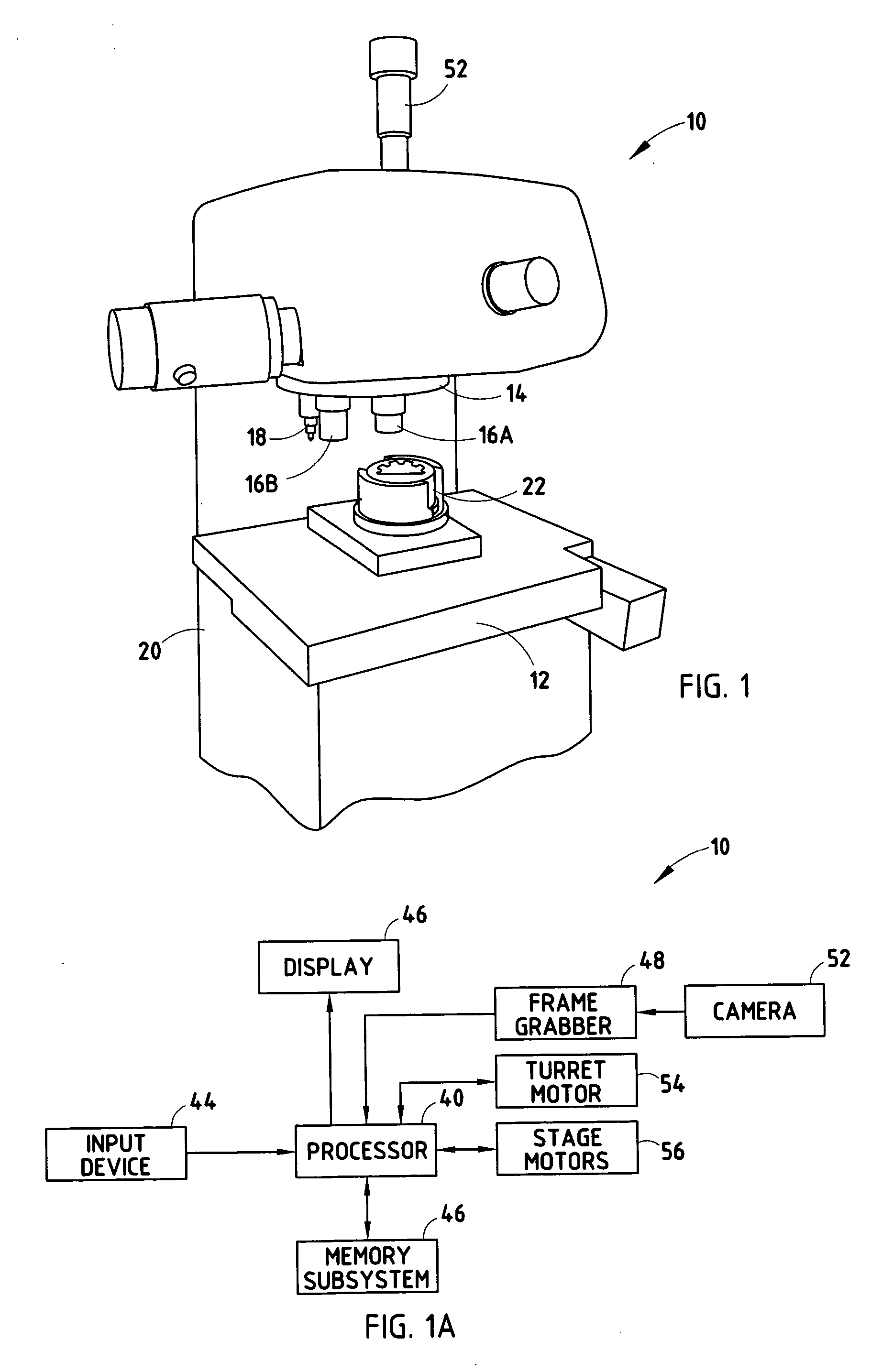
[0024] A system according to various embodiments of the present invention can be implemented using an indentation hardness tester that includes: a light microscope, a digital camera positioned to collect images through the microscope, an electrically controlled stage capable of moving a test assembly, i.e., an associated part to be tested or a portion of a part mounted in a plastic, in at least two dimensions in a plane perpendicular to the lens of the light microscope, and a processor (or computer system) connected to both the camera and the stage such that the processor can display images acquired by the camera while monitoring and controlling the movements of the stage and its associated part.

[0025]FIG. 1 shows a partial perspective view of an exemplary indentation hardness tester according to one embodiment of the present invention. The indentation hardness test system 10 includes a frame 20 with an attached motorized turret 14, including objective lenses 16A and 16B, which for...


PUM


Abstract

An indentation hardness test system includes a frame including an attached indenter, a movable stage for receiving a part attached to the frame, a camera, a display, a processor and a memory subsystem. The camera captures images of the part, which can then be provided on the display. The processor is coupled to the movable stage, the camera and the display, as well as the memory subsystem. The memory subsystem stores executable code that instructs the processor to capture a series of real-time images of the part using the camera, obtain associated stage coordinates for each of the images and display a composite image, which includes the series of real-time images assembled according to the associated stage coordinates, of the part.

Description

[0001] This application is a continuation of U.S. patent application Ser. No. 10 / 679,823, entitled “MICRO HARDNESS TEST SYSTEM,” filed Oct. 6, 2003, which claims the benefit of United States Provisional Patent Application Ser. No. 60 / 419,475, entitled “MICRO HARDNESS TEST SYSTEM,” which was filed Oct. 18, 2002. U.S. patent application Ser. No. 10 / 679,823 is hereby incorporated herein by reference in its entirety.[0002] A portion of the disclosure of this patent document contains material, which is subject to copyright protection. The copyright owner has no objection to the facsimile reproduction by anyone of the patent document or the patent disclosure, as it appears in the Patent and Trademark Office patent file or records, but otherwise reserves all copyright rights whatsoever. REFERENCE TO COMPUTER PROGRAM LISTING APPENDIX [0003] A computer program listing appendix on one compact disc (labeled “Computer Program Listing Appendix—Disc 1 / Copy 1”) includes the following files: File ...

Claims


Application Information

Patent Timeline
IPC IPC(8): G01N3/00G01N3/06G01N3/08G01N3/42
CPCG01N3/08G01N2203/0647G01N2203/0076G01N3/42G01N3/48
Inventor HAUCK, JOHN MICHAELBARFOOL, DAVID ANDREW
Owner LECO CORPORATION
Why Eureka
Try Eureka