Rearview assembly having an integral crush zone

a rearview assembly and crush zone technology, applied in the field of rearview assemblies having a crush zone, can solve the problems of affecting the quality of mirrors, affecting the appearance of mirrors, vibration, unacceptable resonance, etc., and reducing the number of reinforcement ribs, adding to the weight of parts, adding sinks and blemishes,

Active Publication Date: 2005-12-08
GENTEX CORP
View PDF99 Cites 59 Cited by
  • Summary
  • Abstract
  • Description
  • Claims
  • Application Information

AI Technical Summary

Benefits of technology

[0015] A further aspect of the present invention is to provide a rearview assembly for a vehicle comprising a rearview element having a front surface, a rearview element housing having at least a portion of the rearview element therein and a mount for connecting the rearview element and the rearview element housing to a windshield of ...

Problems solved by technology

Since most vehicle mirrors are supported from one side (usually a back or top side), this added weight creates a pendulum effect that causes the mirrors to shake, vibrate, and resonate unacceptably.
However, any increase in wall thickness and/or increase in the number of reinforcement ribs adds to part weight, adds to sinks and blemishes and other quality problems when molding the parts, and adds to part complexity.
Further, the added ribs take up substantial space, making a profile of the mirrors much larger.
However, the adjustable connectors include a plurality of separate parts and pieces t...

Method used


Image

  • Rearview assembly having an integral crush zone
  • Rearview assembly having an integral crush zone
  • Rearview assembly having an integral crush zone

Examples


first embodiment

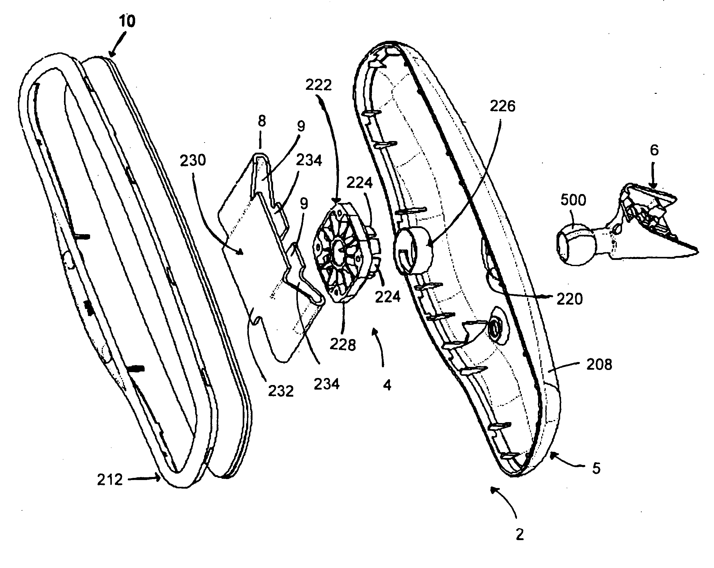
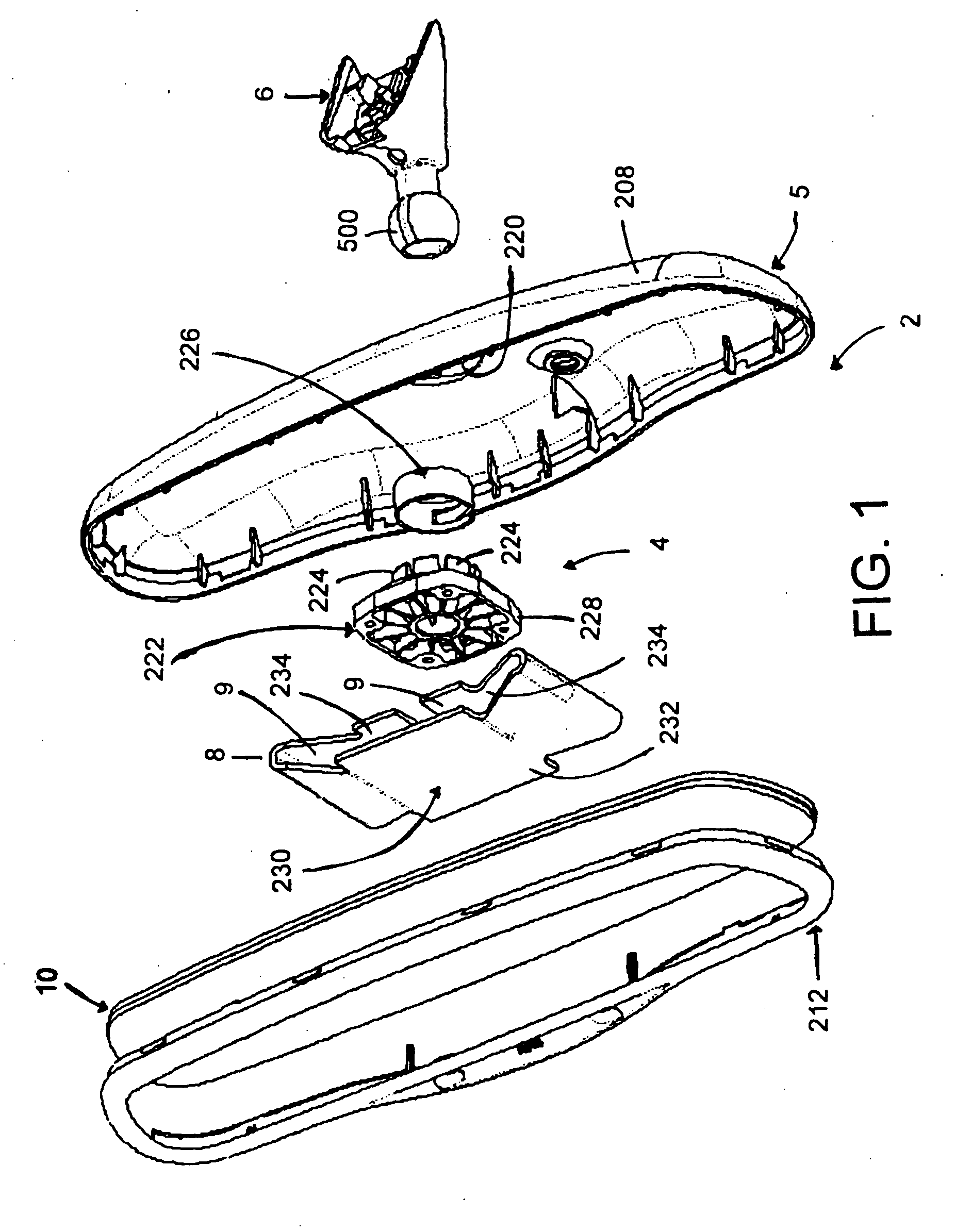
[0053] The reference number 2 (FIG. 1) generally designates a rearview assembly for a vehicle embodying the present invention. The rearview assembly 2 comprises a rearview element 10, a housing comprising a rear housing member 208 and a bezel 212, a rearview element support assembly 4 supporting the rearview element 10 in the housing and a mount 6. The mount 6 is configured to connect the rearview assembly 2 to a windshield. At least one of the rearview element support assembly 4 and the mount 6 comprises a crush bracket 8 having at least two legs 9 adapted to be compressed as a force strikes a front of the rearview element 10.

The Rearview Element

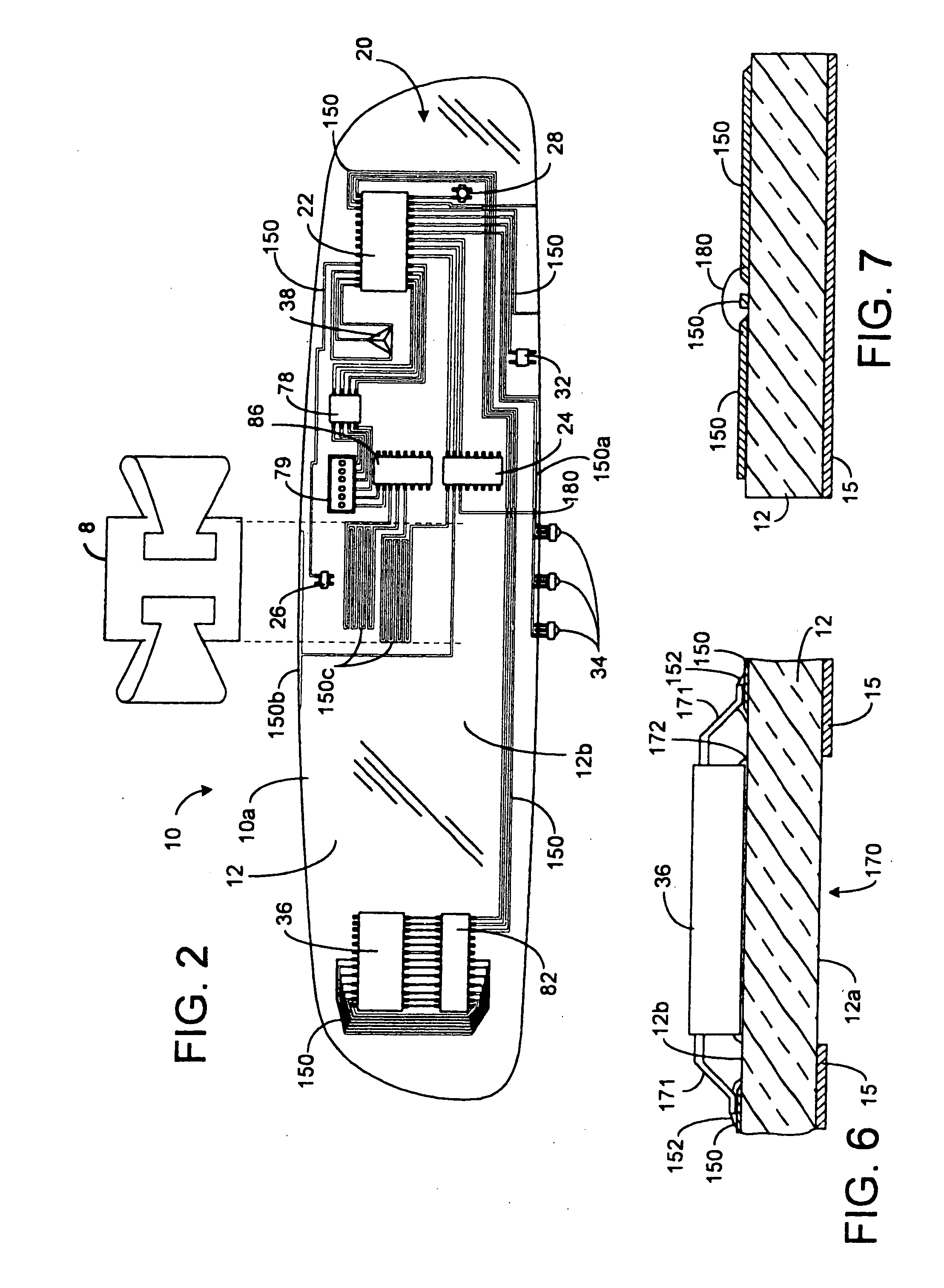
[0054] In a first illustrated embodiment, the rearview element 10 (FIGS. 2 and 3A) of the present invention comprises a reflective element including a first substrate 12 having a front surface 12a and a rear surface 12b, a reflective coating 15 disposed on one of the front surface 12a or the rear surface 12b of the first substrate 12, and...

second embodiment

[0105]FIG. 3B shows the electrochromic rearview element 10b, which eliminates the bus clips 19a and 19b and the wire 13. Instead, the seal 16 is made of an electrically conductive seal material 162 and is provided along the edge of the electrochromic rearview element 10b. As shown, the electrically conductive seal material 162 is provided that not only seals the chamber between substrates 12 and 14, but also provides an electrical connection to the electrodes (the reflective coating 15 and the transparent conductive layer 17). The conductive seal material 162 may also be applied to the rear surface 12b of the substrate 12 to thereby provide the tracings 150a and 150b, which are coupled to terminals of the drive circuit 24 (which is mounted to the rear surface 12b). The portion of the conductive seal material 162 comprising the tracings 150a and 150b may serve to bond the drive circuit 24 to the rear surface 12b. Additional adhesive material may be used if needed. A metal foil 160 is...

third embodiment

[0108]FIG. 3C illustrates the electrochromic rearview element 10c, wherein the first substrate 12 is a separate glass substrate from that used as the rear substrate of the rearview element 10a. In other words, with respect to an electrochromic rearview element, the second substrate 14 may be secured to a third substrate 120 (FIG. 3C) to form a sealed chamber therebetween for containing an electrochromic medium. In this embodiment, first substrate 12 may be separately formed with its associated electronic components and tracings provided on the rear surface 12b and subsequently bonded to the rear surface of the third substrate 120. This embodiment offers the advantages of providing a surface that is more likely to have a uniform flatness and thereby provide better uniformity of the traces. In addition, this embodiment may utilize a cheaper form of glass for either the first substrate 12 or the third substrate 120. Such a separate first substrate 12 would adhere well to the rear subst...


PUM


Abstract

A rearview assembly comprising a rearview element, a rearview element support assembly supporting the rearview element and a mount adjacent the housing. The mount is configured to connect the rearview assembly to a windshield. At least one of the rearview element support assembly and the mount comprises a crush bracket having at least two legs adapted to be compressed as a force strikes a front of the rearview element. The crush bracket can include at least one tab contacting a heat emitting component and/or an electrically conductive component of a circuit to provide a heat sink for the heat emitting component or a ground for the electrically conductive component, respectively.

Description

CROSS-REFERENCE TO RELATED APPLICATION [0001] This application is a continuation-in-part of U.S. patent application Ser. No. 10 / 863,638 which was filed on Jun. 8, 2004 and entitled “REARVIEW MIRROR ELEMENT HAVING A CIRCUIT MOUNTED TO THE REAR SURFACE OF THE ELEMENT.”BACKGROUND [0002] The present invention concerns vehicle mirrors, and more particularly relates to a rearview assembly having an integral crush zone. [0003] Interior and exterior rearview mirrors of modern passenger vehicles have become heavier and heavier as more and more content and features are added. For example, many modern vehicle mirrors include several of the following options: electrochromic mirror subassemblies and circuitry to reduce glare, keyless entry sensing systems, microphone-speaker-antennae-phone communication systems, audio-control systems, compass and temperature devices and displays, lighting, switches for control of electrical circuits, and the like. Since most vehicle mirrors are supported from on...

Claims


Application Information

Patent Timeline
IPC IPC(8): B60R1/08B60R1/12G02B27/00G02F1/15H05K1/02H05K1/03H05K3/32
CPCB60R1/088B60R1/12H05K1/0274H05K1/0306H05K3/321H05K2201/0108H05K2201/10651H05K2201/2036H05K2201/2054H05K2201/10106
Inventor BAUER, FREDERICK T.BOSTWICK, DANIEL J.RUMSEY, WAYNE J.TURNBULL, ROBERT R.WATSON, ALAN R.
Owner GENTEX CORP
Why Eureka
Try Eureka