Ink jet printer

Inactive Publication Date: 2005-12-15
BROTHER KOGYO KK
View PDF7 Cites 8 Cited by
  • Summary
  • Abstract
  • Description
  • Claims
  • Application Information

AI Technical Summary

Benefits of technology

[0012] An object of the present invention is to present an ink jet printer wherein ink that was jetted onto an ink receiving sheet during a purge process can be discarded easily.
[0016] As a result, the self-weight of the ink jetted onto the ink receiving sheet during a purge process allows this ink to flow rapidly down the ink receiving sheet, and the ink can easily be collected in the ink collecting mechanism.
[0017] In this ink jet printer, only the ink stored in the ink collecting mechanism needs to be discarded. The complex operation of exchanging the ink receiving sheet or the ink collecting body, as in the conventional case, is not required. The ink can be discarded easily.

Problems solved by technology

When these occur, the jetting characteristics of the ink are disturbed, and satisfactory printing quality cannot be obtained.
Ink absorbing capability is limited in all these techniques, and the component that absorbs the ink must be exchanged frequently.
Since exchanging the ink receiving sheet or the ink collecting body is a complex operation, maintenance of the ink jet printer is extremely time-consuming.

Method used


Image

  • Ink jet printer
  • Ink jet printer
  • Ink jet printer

Examples


Embodiment Construction

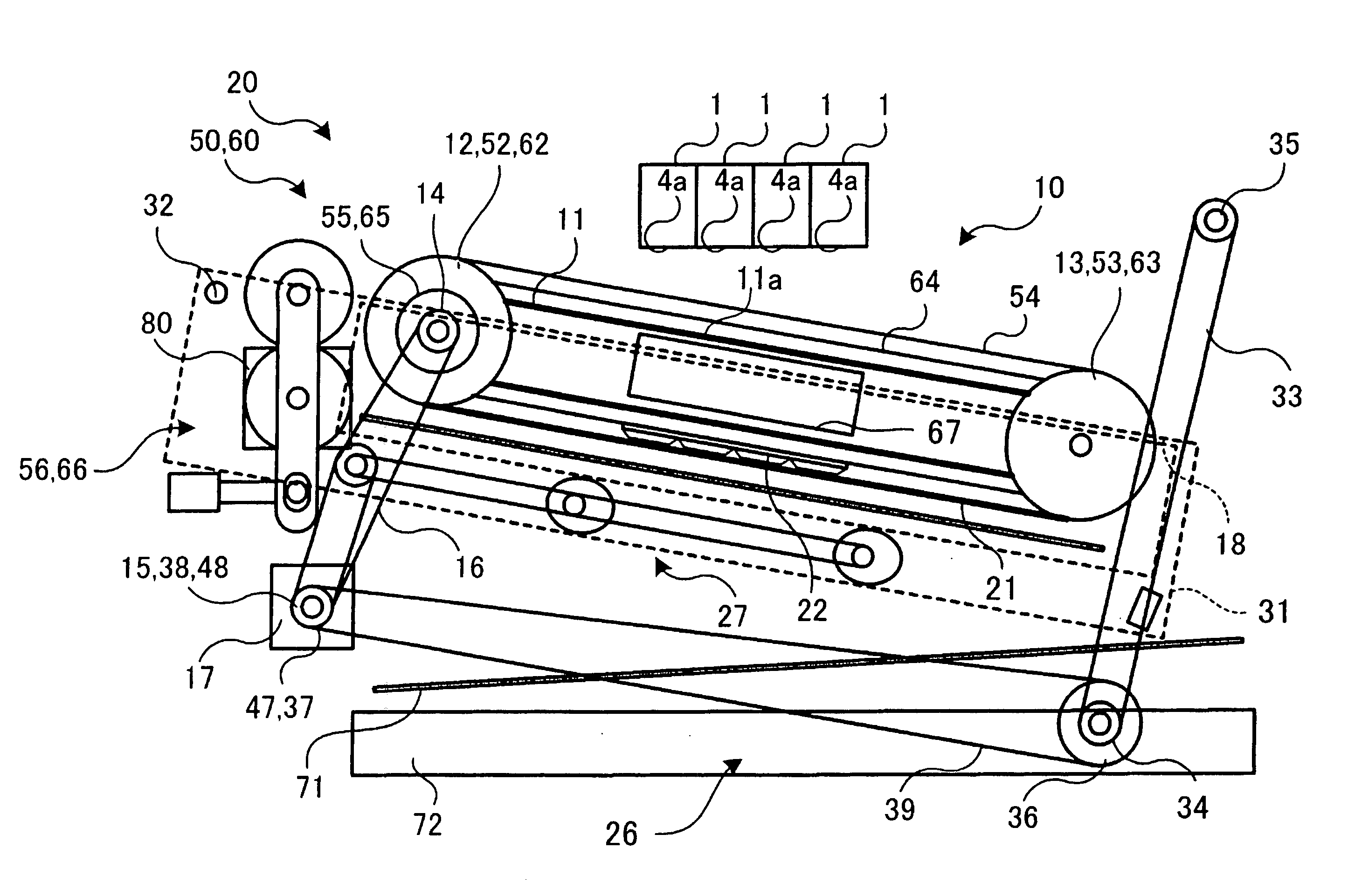
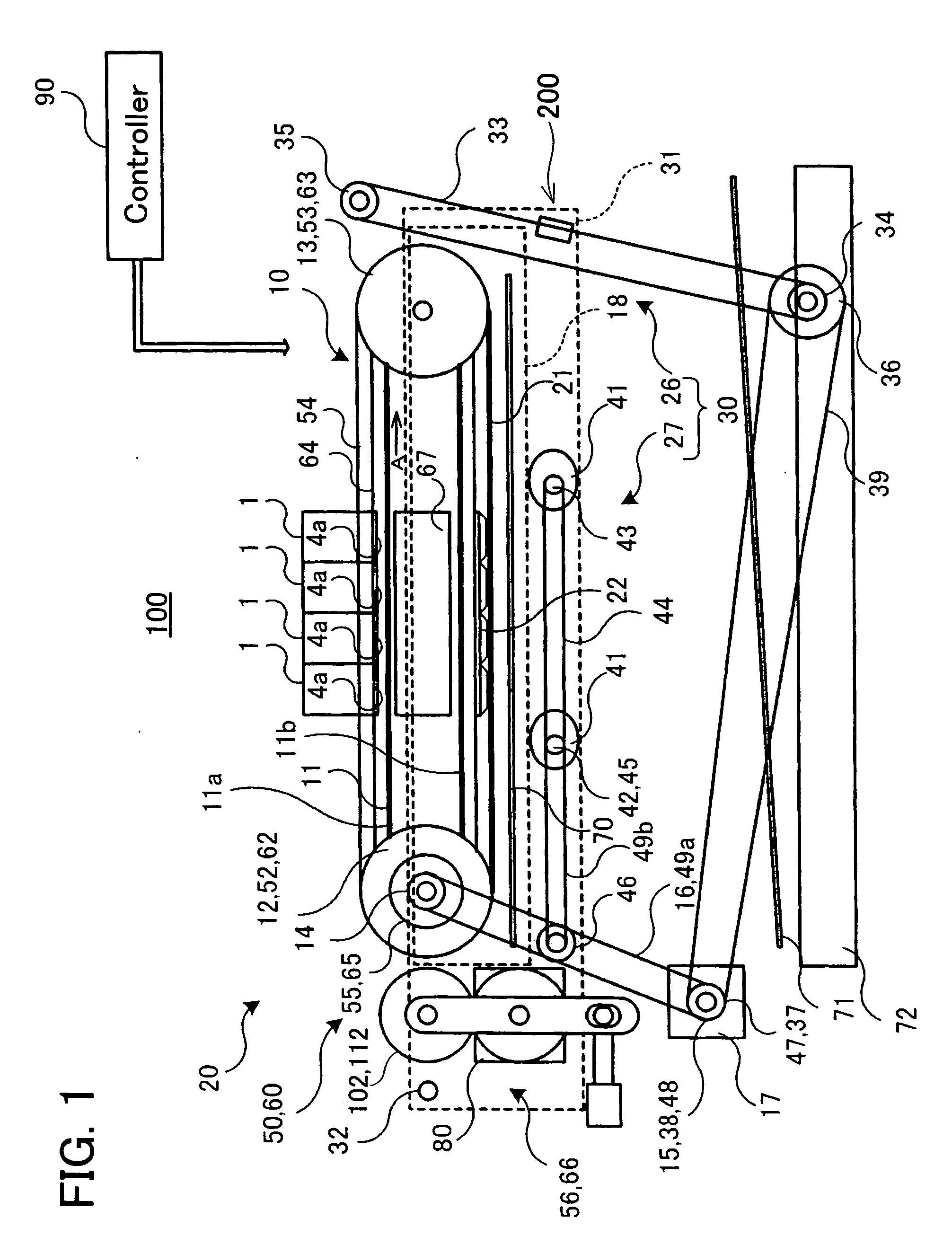
[0040] A preferred representative embodiment of the present teachings will be described below with reference to the drawings. FIG. 1 shows a schematic diagram of an ink jet printer of a representative embodiment of the present teachings. FIG. 1 shows the ink jet printer engaged in a printing operation.

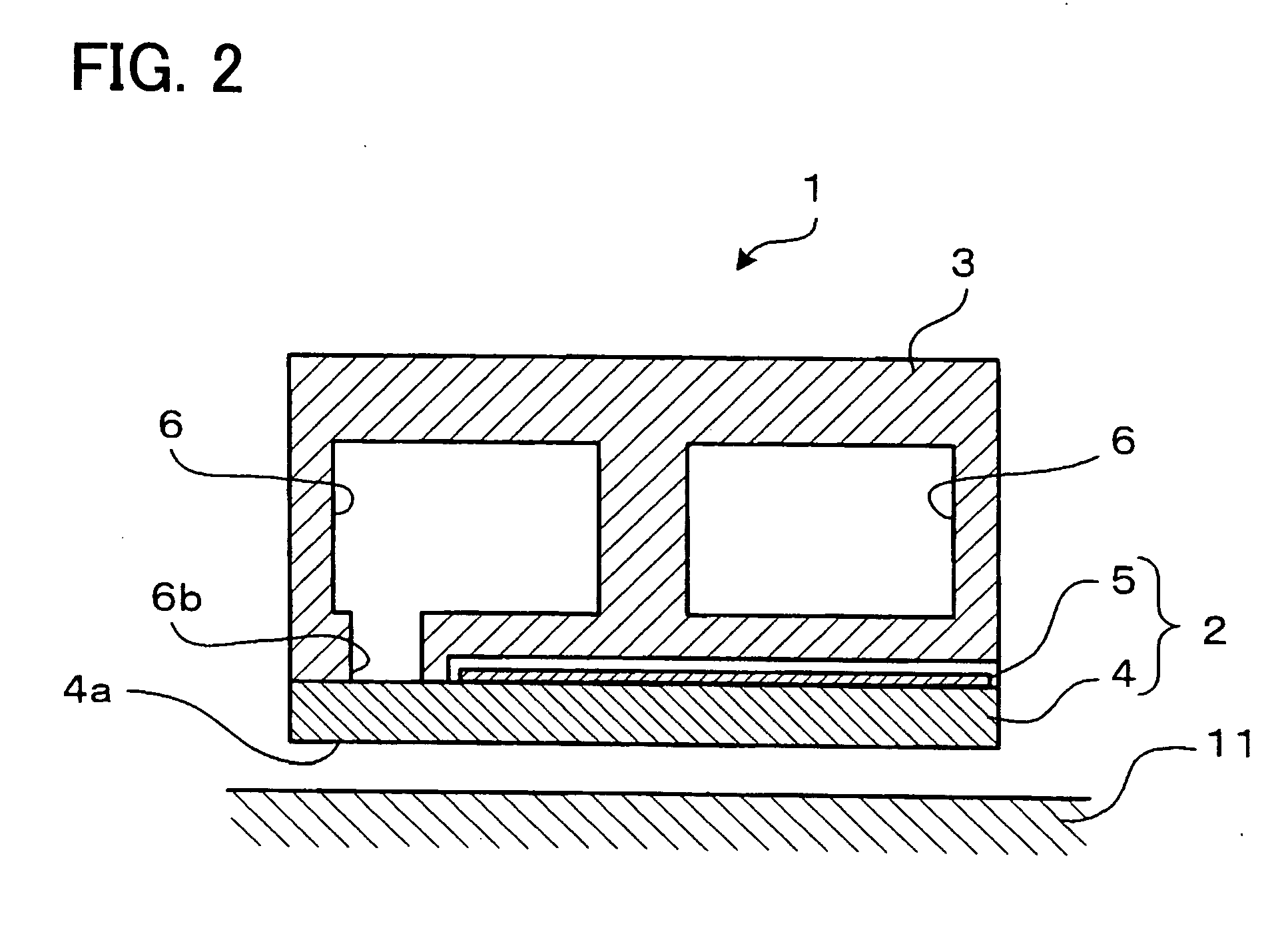
[0041] The ink jet printer 100 forms a desired image on a printing sheet by jetting ink droplets onto the printing sheet, and includes four ink jet heads 1 for jetting the ink droplets, a feeding sheet 11 for supporting the printing sheet, a feeding sheet conveying mechanism 10, a maintenance mechanism 20 for performing maintenance of the ink jet printer 100, and a controller 90 for controlling operations of the ink jet printer 100.

[0042] The feeding sheet 11 and the feeding sheet conveying mechanism 10 are mounted in a unit 200. The unit 200 includes a swing frame 31 and a lift frame 18. The feeding sheet 11 and the feeding sheet conveying mechanism 10 are supported by the lift fram...


PUM

PropertyMeasurementUnit
Lengthaaaaaaaaaa
Poweraaaaaaaaaa
Diameteraaaaaaaaaa

Abstract

In order to make maintenance of an ink jet printer less time-consuming, when ink is to be purged from ink jet heads 1, a unit conveying mechanism 30 moves a feeding plane 11a of a feeding sheet 11 to a retreated position that is inclined with respect to ink jet faces 4a of the ink jet heads 1. An ink receiving sheet 21 is then moved to an ink receiving position that is between the ink jet faces 4a and the feeding plane 11a and that extends along this feeding plane 11a. Ink that is jetted onto the ink receiving sheet 21 from the ink jet faces 4a of the ink jet heads 1 runs down the ink receiving sheet 21, and is collected in an ink tank 72.

Description

CROSS-REFERENCE TO RELATED APPLICATION [0001] This application claims priority to Japanese Patent Application No. 2004-175436, filed on Jun. 14, 2004, the contents of which are hereby incorporated by reference into the present application. BACKGROUND OF THE INVENTION [0002] 1. Field of the Invention [0003] The present invention relates to an ink jet printer for printing on a printing sheet by jetting ink. [0004] 2. Description of the Related Art [0005] An ink jet printer is provided with an ink jet head. Ink is jetted from the ink jet head. The ink jet head is provided with an ink jet nozzle, a pressure chamber joined with the ink jet nozzle, and an actuator disposed in a position adjacent to the pressure chamber. Capacity of the pressure chamber is reduced when the actuator is driven, and a quantity of ink corresponding to this reduction in capacity is jetted from the ink jet nozzle. The ink jet nozzle, the pressure chamber, and the actuator form a set, and normal ink jet heads are...

Claims


Application Information

Patent Timeline
IPC IPC(8): B41J2/18B41J2/165B41J2/17B41J2/185B41J11/00B41J13/00B41J13/08B65H5/02
CPCB41J2/16523B41J11/007B41J2/1721B41J2/16585
Inventor TAKAGI, OSAMUKUZUYA, SUSUMU
Owner BROTHER KOGYO KK
Why Eureka
Try Eureka