

Zoom lens system and image pickup apparatus having the same
a technology of zoom lens and image pickup, which is applied in the field of zoom lens system, can solve the problems of affecting the composition of the photograph, and the time of the photograph must be sufficiently short, so as to achieve the effect of maintaining the composition setting and avoiding blurring
- Summary
- Abstract
- Description
- Claims
- Application Information
AI Technical Summary
Benefits of technology
Problems solved by technology
Method used
Image

Examples
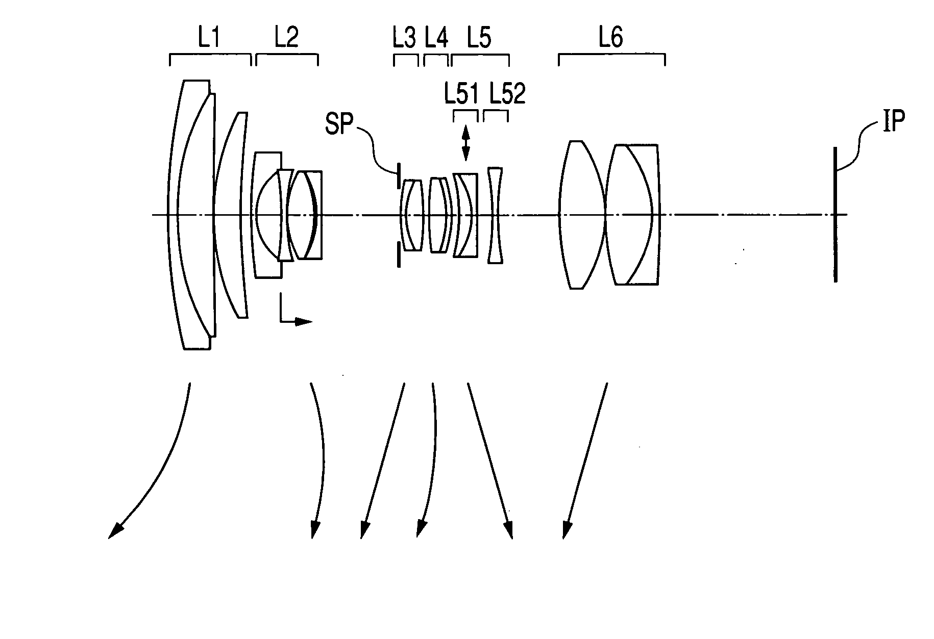
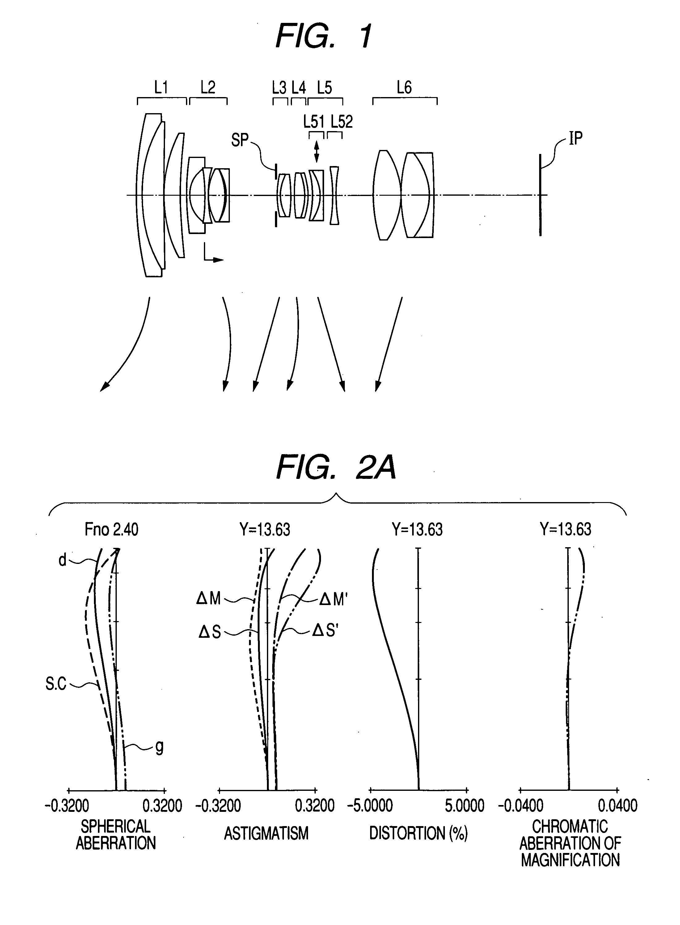
embodiment 1
[0129]
f = 17.51˜82.45 fno. = 1:3.6˜5.77 2ω = 18.2˜75.40r1 = 119.374d1 = 1.80n1 = 1.84666ν1 = 23.9r2 = 49.289d2 = 7.03n2 = 1.72916ν2 = 54.7r3 = 530.863d3 = 0.13n3 = 1.77250ν3 = 49.6r4 = 44.189d4 = 5.17n4 = 1.52421ν4 = 51.4r5 = 123.773d5 = variablen5 = 1.83481ν5 = 42.7*r6 = 92.506d6 = 0.05n6 = 1.80400ν6 = 46.6r7 = 81.956d7 = 1.00n7 = 1.63980ν7 = 34.5r8 = 10.675d8 = 5.23n8 = 1.60311ν8 = 60.6r9 = −55.217d9 = 1.00n9 = 1.80518ν9 = 25.4r10 = 29.689d10 = 0.13n10 = 1.48749ν10 = 70.2r11 = 17.287d11 = 5.38n11 = 1.59551ν11 = 39.2r12 = −20.368d12 = 0.28n12 = 1.80440ν12 = 39.6r13 = −18.241d13 = 1.00n13 = 1.78470ν13 = 26.3r14 = 162.287d14 = variablen14 = 1.65844ν14 = 50.9r15 = stopd15 = 0.25n15 = 1.56384ν15 = 60.7r16 = 29.990d16 = 1.00n16 = 1.58313ν16 = 59.4r17 = 13.243d17 = 3.48n17 = 1.49700ν17 = 81.5r18 = −51.074d18 = variablen18 = 1.84666ν18 = 23.9r19 = 35.922d19 = 3.60r20 = −19.381d20 = 1.00r21 = −26.457d21 = variabler22 = −31.694d22 = 2.53r23 = −13.486d23 = 1.00r24 = 251.469d24 = variabler25 ...
embodiment 2
[0130]
f = 17.51˜82.45 o. = 1:4.1˜5.77 2ω = 18.2˜75.40r1 = 142.785d1 = 1.80n1 = 1.84666ν1 = 23.9r2 = 53.290d2 = 7.40n2 = 1.77250ν2 = 49.6r3 = 1231.404d3 = 0.12n3 = 1.73400ν3 = 51.5r4 = 46.025d4 = 4.30n4 = 1.52421ν4 = 51.4r5 = 97.332d5 = variablen5 = 1.77250ν5 = 49.6*r6 = 85.432d6 = 0.05n6 = 1.77250ν6 = 49.6r7 = 75.790d7 = 1.20n7 = 1.74077ν7 = 27.8r8 = 12.401d8 = 5.63n8 = 1.69680ν8 = 55.5r9 = −53.760d9 = 1.00n9 = 1.83481ν9 = 42.7r10 = 22.931d10 = 0.15n10 = 1.48749ν10 = 70.2r11 = 18.706d11 = 5.10n11 = 1.48749ν11 = 70.2r12 = −42.374d12 = 0.60n12 = 1.84666ν12 = 23.9r13 = −27.795d13 = 1.20n13 = 1.84666ν13 = 23.9r14 = −515.097d14 = variablen14 = 1.72342ν14 = 38.0r15 = stopd15 = 2.50n15 = 1.61272ν15 = 58.7r16 = 32.734d16 = 1.20n16 = 1.58313ν16 = 59.4r17 = 14.965d17 = 3.00n17 = 1.49700ν17 = 81.5r18 = −56.078d18 = 0.15n18 = 1.84666ν19 = 23.9r19 = 22.894d19 = 3.11r20 = −22.753d20 = 1.20r21 = −29.426d21 = variabler22 = −51.462d22 = 2.00r23 = −16.056d23 = 0.80r24 = 63.175d24 = variabler25 = −17....
embodiment 3
[0131]
f = 45.6˜182.9 fno. = 1:4.7˜5.85 2ω = 13.49˜50.79r1 = 58.164d1 = 2.38n1 = 1.48749ν1 = 70.23r2 = 151.636d2 = 0.09n2 = 1.74950ν2 = 35.33r3 = 45.567d3 = 1.39n3 = 1.51633ν3 = 64.14**r4 = 27.997d4 = 6.38n4 = 1.75047ν4 = 52.57r5 = 32265.515d5 = variablen5 = 1.86091ν5 = 37.91r6 = 563.103d6 = 0.63n6 = 1.62227ν6 = 60.15r7 = 53.263d7 = 0.94n7 = 1.84666ν7 = 23.93r8 = 73.823d8 = 0.69n8 = 1.85751ν8 = 34.13r9 = 29.252d9 = 1.21n9 = 1.58313ν9 = 59.4r10 = −34.667d10 = 0.69n10 = 1.73430ν10 = 53.41r11 = 38.419d11 = 0.08n11 = 1.84666ν11 = 23.93r12 = 37.788d12 = 2.04n12 = 1.58313ν12 = 59.4r13 = 1217.756d13 = variablen13 = 1.84666ν13 = 23.93r14 = 19.630d14 = 0.69n14 = 1.48749ν14 = 70.23r15 = 13.291d15 = 3.32n15 = 1.77368ν15 = 50.08*r16 = −61.570d16 = 0.63n16 = 1.74571ν16 = 52.81r17 = stopd17 = variablen17 = 1.63530ν17 = 35.11r18 = −15.425d18 = 1.20n18 = 1.83481ν18 = 42.72r19 = 26.979d19 = 1.67n19 = 1.84666ν19 = 23.78r20 = −186.019d20 = variabler21 = 63.786d21 = 2.81*r22 = −29.717d22 = 0.09r23 = 494...
PUM
 Abstract
Description
Claims
Application Information