Area light source device and liquid crystal display apparatus

Inactive Publication Date: 2005-12-15
JAPAN DISPLAY CENT INC
View PDF2 Cites 0 Cited by
  • Summary
  • Abstract
  • Description
  • Claims
  • Application Information

AI Technical Summary

Benefits of technology

[0010] The present invention has been made in consideration of the above-described problem, and the object of the invention is to provide an area light sour

Problems solved by technology

As a result, bending or waviness tends to occur on the reflective sheet.
In the case where the above-described reflective sheet is directly disposed on the back surface of the light guide, the following problem may arise.
If each of the contact part and non-contact part has a relatively large area, non-uniformity in luminance may be caused on the light emission surface of the light guide.
In the liquid crystal display apparatus including such an area light source device, non-uniformity in luminance may be visually recognized and the display quality may deteriorate.
Thereby, the area of the contact part is reduced, and non-uniformity in luminance

Method used


Image

  • Area light source device and liquid crystal display apparatus
  • Area light source device and liquid crystal display apparatus
  • Area light source device and liquid crystal display apparatus

Examples


Example

[0022] An area light source device according to an embodiment of the present invention and a liquid crystal display apparatus including the area light source device will now be described with reference to the accompanying drawings.

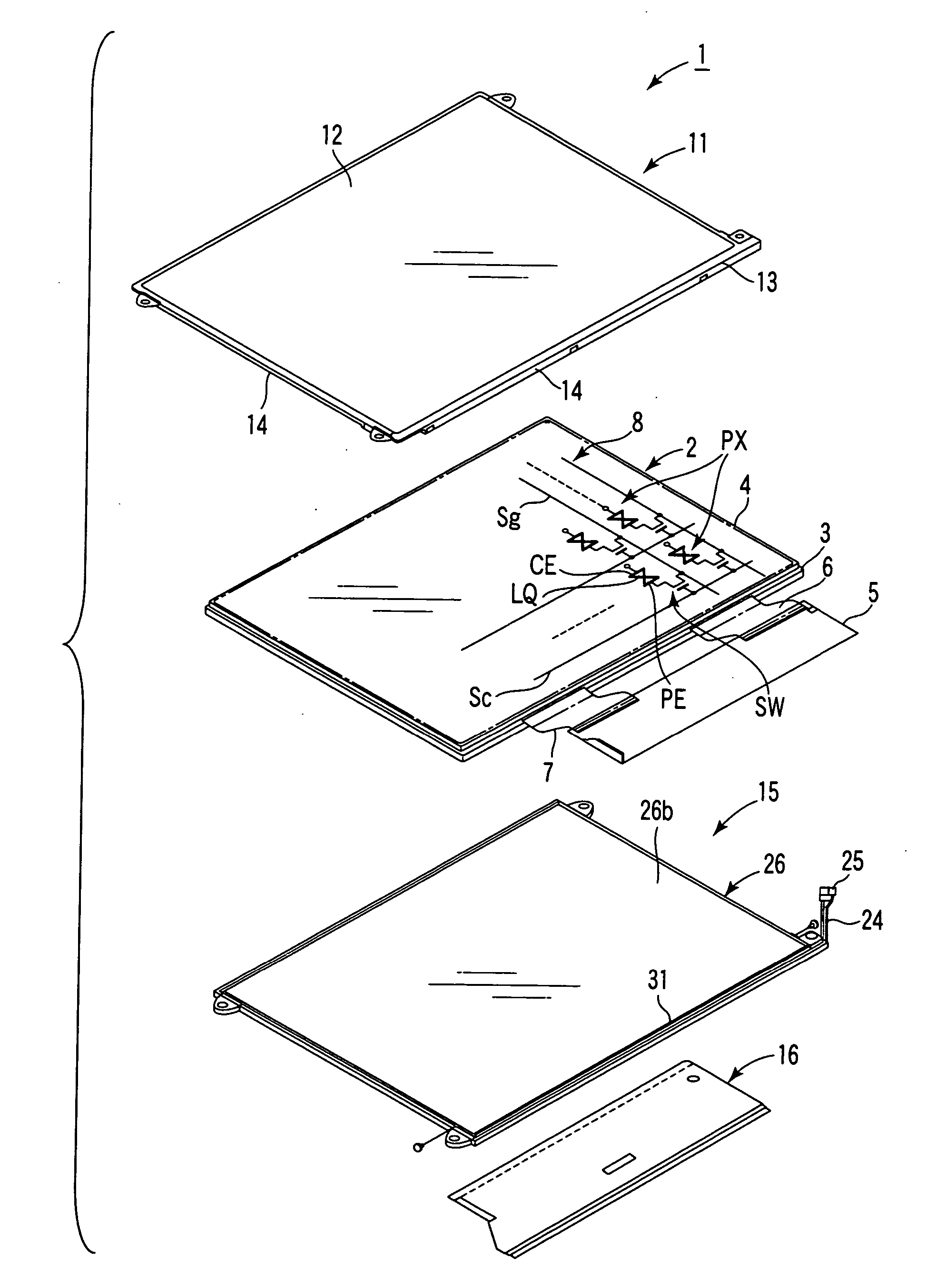
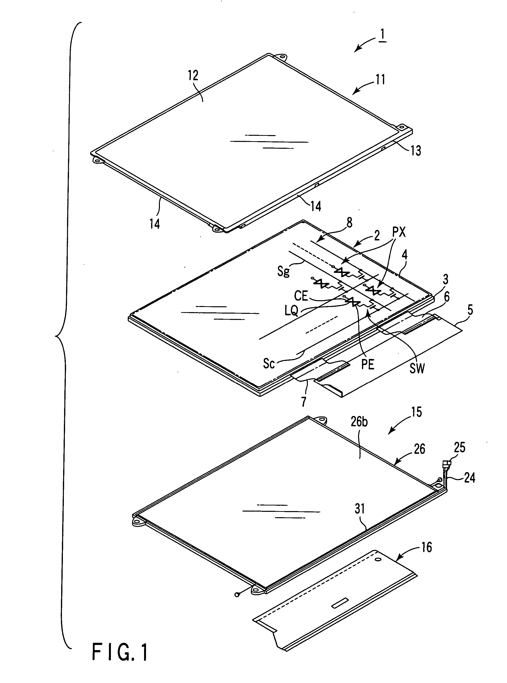
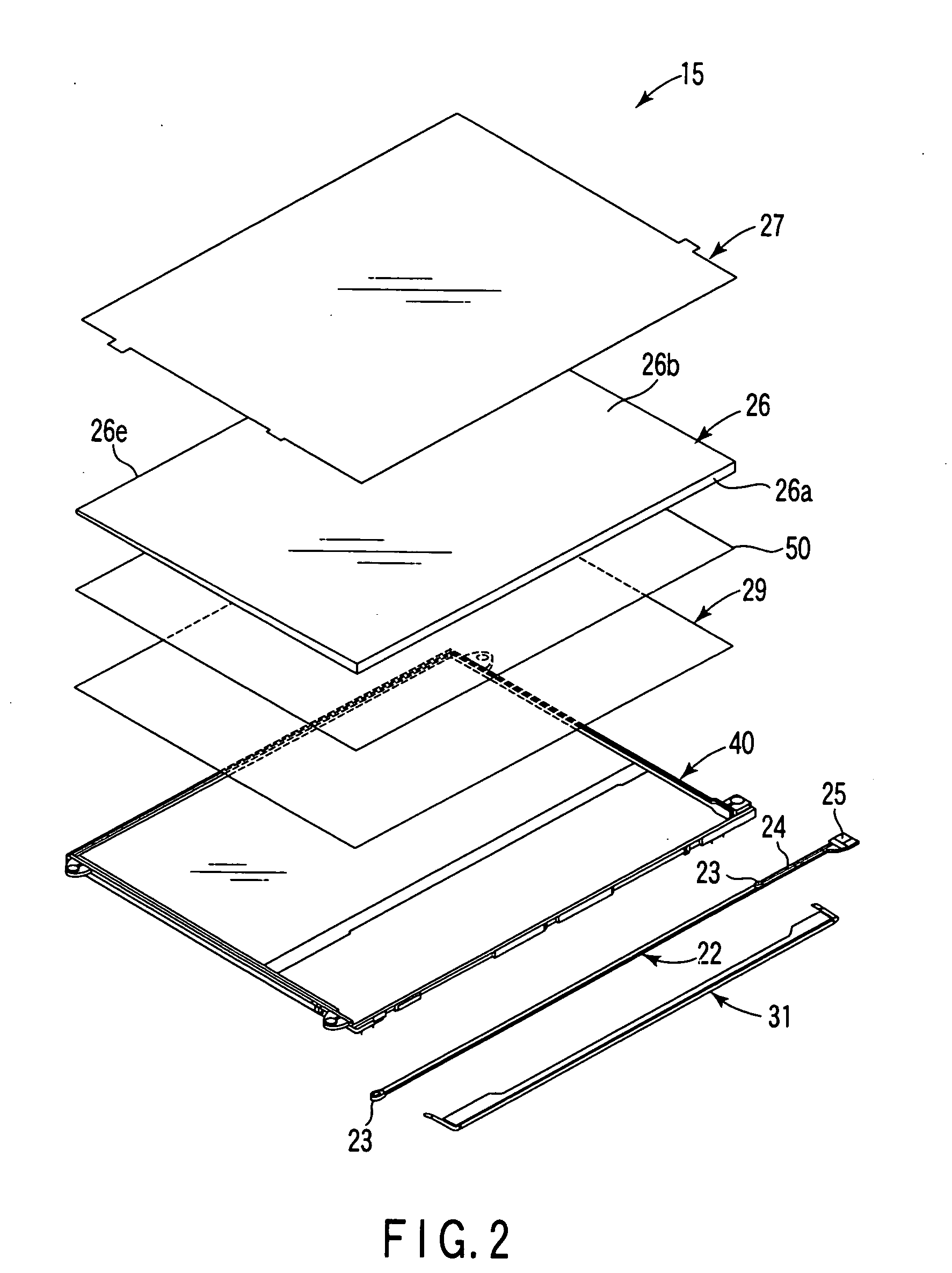
[0023] As is shown in FIG. 1, a liquid crystal display apparatus 1 includes a substantially rectangular, planar transmissive liquid crystal display panel 2. The liquid crystal display panel 2 is configured such that a liquid crystal layer LQ that serves as an optical modulation layer is interposed between a pair of substrates, that is, an array substrate 3 and an counter substrate 4. The liquid crystal display panel 2 includes a substantially rectangular effective display section 8 that displays an image. The effective display section 8 is composed of a plurality of display pixels PX that are arranged in a matrix.

[0024] The array substrate 3 includes switching elements SW, such as thin-film transistors, which are arranged near intersections between scan ...


PUM


Abstract

An area light source device includes a light source, a light guide including a first side surface on which emission light from the light source is incident, and a first major surface and a second major surface, which are opposed to each other and from which the incident light on the first side surface emerges, an optical sheet that is disposed on the second major surface side of the light guide and has a reflective surface on a side thereof that is opposed to the second major surface, and a film member that is disposed between the light guide and the optical sheet, has light transmissivity and has a projection-and-recess-shaped portion on a surface thereof.

Description

CROSS-REFERENCE TO RELATED APPLICATIONS [0001] This application is based upon and claims the benefit of priority from prior Japanese Patent Application No. 2004-176864, filed Jun. 15, 2004, the entire contents of which are incorporated herein by reference. BACKGROUND OF THE INVENTION [0002] 1. Field of the Invention [0003] The present invention relates to an area light source device that illuminates a liquid crystal display panel and to a liquid crystal display apparatus including the area light source device. [0004] 2. Description of the Related Art [0005] Recently, in an increasing number of liquid crystal display apparatuses that selectively pass emission light from area light source devices and display images, a reflective sheet is disposed on the back side of a light guide in order to improve the efficiency of use of emission light from the area light source device and to meet a demand for higher luminance. The reflective sheet is, for instance, a film whose basic material is p...

Claims


Application Information

Patent Timeline
IPC IPC(8): F21V7/04F21V8/00
CPCG02B6/0053G02F1/1335
Inventor TSUKAMOTO, TAKAYOSHI
Owner JAPAN DISPLAY CENT INC
Why Eureka
Try Eureka