Gas discharge tube

Inactive Publication Date: 2005-03-03
HAMAMATSU PHOTONICS KK
View PDF16 Cites 0 Cited by
  • Summary
  • Abstract
  • Description
  • Claims
  • Application Information

AI Technical Summary

Benefits of technology

[0017] In the gas discharge tube, the first discharge path-limit portion and the second discharge path-limit portion are electrically insulated from each other in order to make a starting properties of a lamp excellent even if the discharge path is narrowed. Thereby, the first discharge path-limit portion and the second discharge path-limit portion can be set to different potentials. Therefore, by adjusting each potential, discharge at a starting time is facilitated to pass through the inside of the second opening. As a result, discharge between the cathode portion and the anode portion is started rapidly. Therefore, in order to achieve a further enhancement of luminance, there can be accomplished with ease a further miniaturization, of the opening, in terms of its area size, in the discharge path-limit portion while the starting properties being kept excellent without any increase in the voltage at the time of lamp starting so much.
[0018] Further, it is preferable that the second discharge path-limit portion is shielded from the cathode portion by an insulating material. With such a constitution, there is prevented occurrence of an abnormal discharge due to bending around-discharge extending from the cathode portion toward the second discharge path-limit portion.
[0019] Furthermore, it is preferable that an annular spacer of insulating material for positioning the second discharge path-limit portion and the anode portion is provided between the second discharge path-limit portion and the anode portion. With such a constitution, improvement in positioning accuracy between the second discharge path-limit portion and the anode portion can be achieved.
[0020] Moreover, it is preferable that the gas discharge tube further comprises a third discha

Problems solved by technology

In the gas discharge tube, in case where light with high luminance is to be created, it is insufficient to simply make an opening portion for narrowi

Method used


Image

  • Gas discharge tube
  • Gas discharge tube
  • Gas discharge tube

Examples


Example

[0039] [First Embodiment]

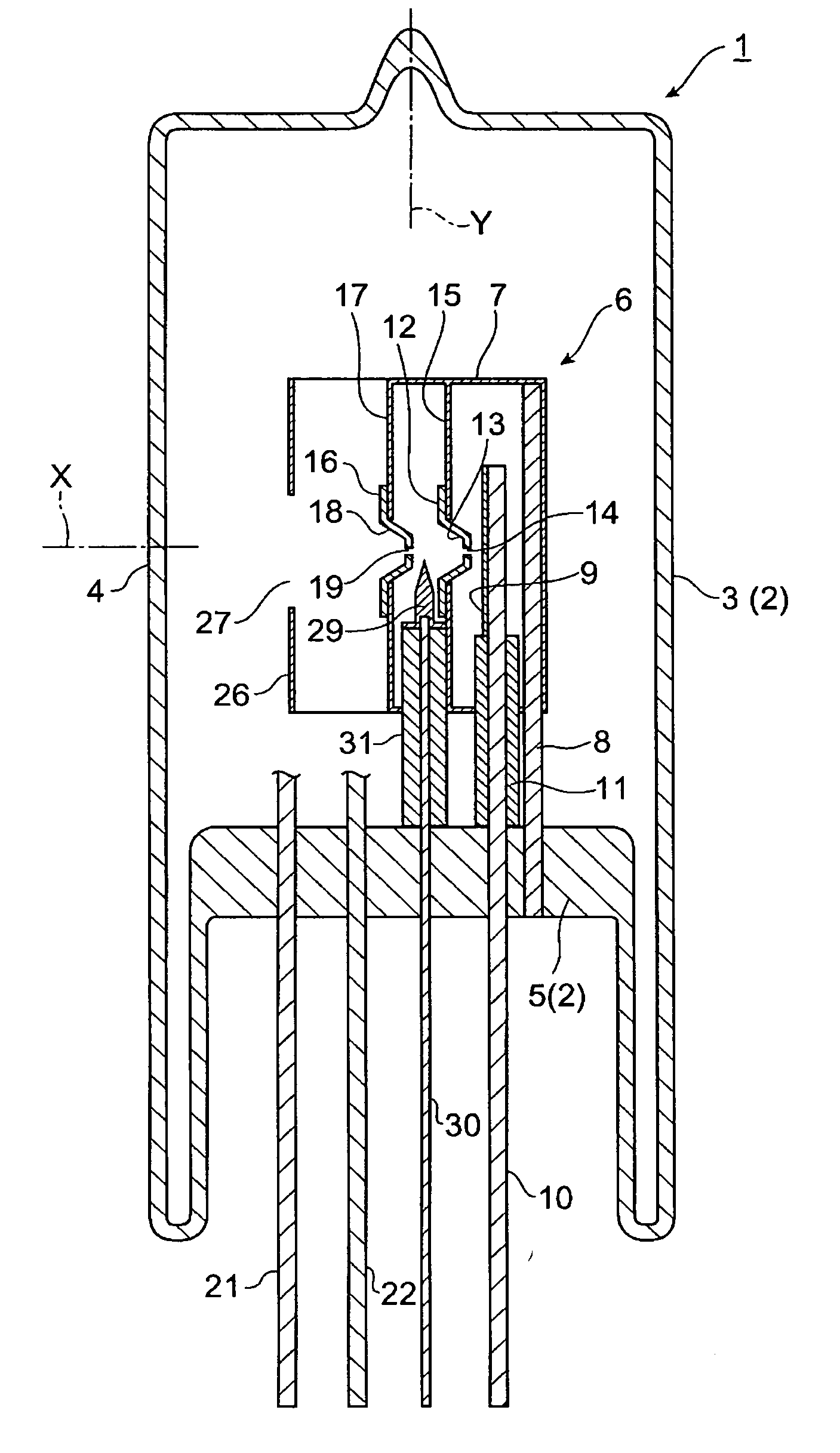
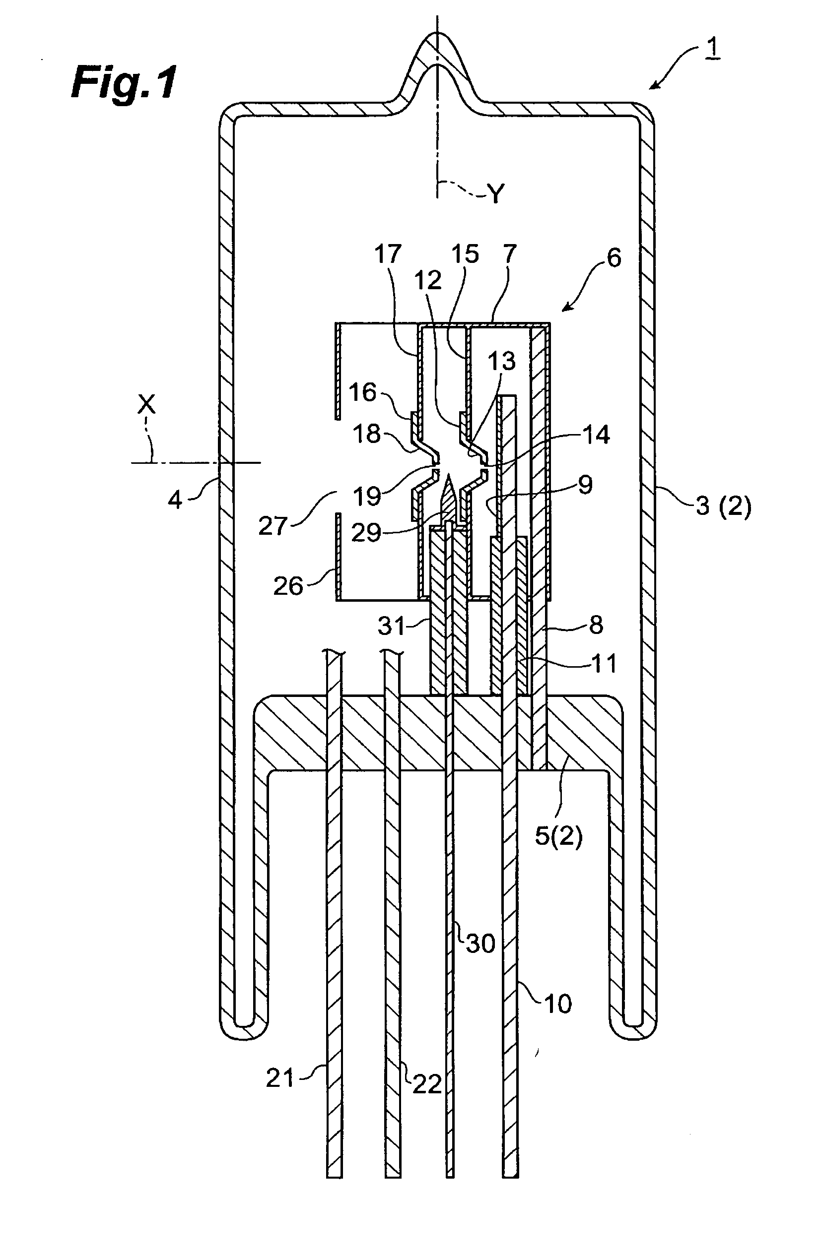
[0040] As shown in FIG. 1 and FIG. 2, a gas discharge tube 1 is a deuterium lamp of a side-on type, and the discharge tube 1 has a sealed container 2 made of glass in which deuterium gas is enclosed in an amount of about several hundreds Pa. This sealed container 2 comprises a cylindrical side tube 3 whose one end side is sealed and a stem 5 for sealing the other end side of the side tube 3, and one portion of the side tube 3 is utilized as a light emitting window 4. Then, a light emitting assembly 6 is accommodated inside the sealed container 2.

[0041] The light emitting assembly 6 has an electrically conductive casing 7 made of metal such as nickel or the like, and the casing 7 is welded and fixed to a distal end of a stem pin 8 which is provided on the stem 5 upstanding so as to extend in Y direction of a tube axis. Further, a plate-like anode portion 9 is accommodated inside the light emitting assembly 6, and the anode portion 9 is welded and fixed to a ...

Example

[0053] [Second Embodiment]

[0054] As shown in FIG. 3 and FIG. 4, a gas discharge tube 34 is a deuterium lamp of a side-on type. The gas discharge tube 34 is different from the first embodiment in that three discharge path-limit portions are provided, and identical or similar constitution elements therein are designated with same reference numerals and explanation thereof will be omitted.

[0055] A third discharge path-limit portion 36 is accommodated between the second discharge path-limit portion 12 and the anode portion 9 in the casing 7 of the gas discharge tube 34, and the third discharge path-limit portion 36 is welded and fixed to the casing 7 via an electrically conductive supporting plate 37 made of metal. The third discharge path-limit portion 36 is made of electrically conductive metal (for example, molybdenum, tungsten, or alloy made of these materials) and has a cup portion 38 for forming an arc ball, and this cup portion 38 is spread toward the light emitting window 4 so ...

Example

[0057] [Third Embodiment]

[0058] As shown in FIG. 5 and FIG. 6, a gas discharge tube 40 is a deuterium lamp of a side-on type, and the gas discharge tube 40 is identical to the second embodiment in that the three discharge path-limit portions 12, 16 and 36 are provided, while there is a difference in such an arrangement that the second discharge path-limit portion 12 and the third discharge path-limit portion 36 come closer to each other. As a result of such an arrangement that the second discharge path-limit portion 12 and the third discharge path-limit portion 36 come closer to each other at a distance of, for example, 0.1 mm to 1 mm there between in this manner, spreading of discharge can be suppressed at a location of the discharge path positioned between the second opening 14 and the third opening 39, so that the starting properties can be made better and luminance can be enhanced.


PUM


Abstract

In a gas discharge tube, a first discharge path-induction portion is arranged between a first discharge path-limit portion and a second discharge path-limit portion. A voltage is applied to the first discharge path-induction portion from the outside. As a result, an active starting discharge capable of passing through a first opening of the first discharge path-limit portion is produced between a cathode portion and the first discharge path-induction portion. As a consequence, there is facilitated the discharge at a starting time to pass through a second opening. As a consequence, there is achieved a rapid starting of discharge between the cathode portion and an anode portion. Therefore, in order to achieve further enhancement of brightness, there can be carried out with ease a further miniaturization pertaining to the openings, in terms of its area size, of the discharge path-limit portion while the starting properties being kept excellent, without any increase in a voltage at the starting time of the lamp so much.

Description

TECHNICAL FIELD [0001] The present invention relates to a gas discharge tube, and in particular to a gas discharge tube used as a light source for a spectroscope, a chromatography or the like. BACKGROUND ART [0002] There is disclosed as a prior art pertaining to the related technical field a gas (deuterium) discharge tube in Japanese Patent Laid-Open No.6-310101 publication. In a gas (deuterium) discharge tube described in this publication, there are arranged two metal partition walls within the discharge path between an anode and a cathode, wherein each of the metal partition walls is provided with small holes, whereby the discharge path is caused to be narrowed. As a result, it is made possible to obtain light with a high luminance by means of the small holes on the discharge path. Further, provision of three or more metal partition walls could lead to a further higher luminance. The smaller holes are made, the higher luminance of light there can be obtained. DISCLOSURE OF THE INV...

Claims


Application Information

Patent Timeline
IPC IPC(8): H01J61/10H01J61/54H01J61/68
CPCH01J61/54H01J61/68H01J61/545
Inventor ITO, YOSHINOBU
Owner HAMAMATSU PHOTONICS KK
Why Eureka
Try Eureka