
Network management system, and network management method

a network management system and network management technology, applied in the field of network management system and network management method, can solve the problems of inability to collect user network details, difficulty in collectively managing all user networks through operation management server, and inability to manage user networks

Inactive Publication Date: 2005-12-15
FUJITSU LTD
View PDF19 Cites 15 Cited by
  • Summary
  • Abstract
  • Description
  • Claims
  • Application Information

AI Technical Summary

Benefits of technology

[0029] It is an object of the present invention to solve the problems, and to provide a technology for collectively managing user networks connected to a v

Problems solved by technology

Moreover, because of such circumstances, there is a problem in that it is difficult to collectively manage all of the user networks by use of the operation management server 10.
However, in this technology, the standard MIBs of the CE routers, which are the detailed information regarding the user networks, cannot be collected.
Information collection for the MIBs regarding the user network

Method used


Image

  • Network management system, and network management method
  • Network management system, and network management method
  • Network management system, and network management method

Examples


first embodiment

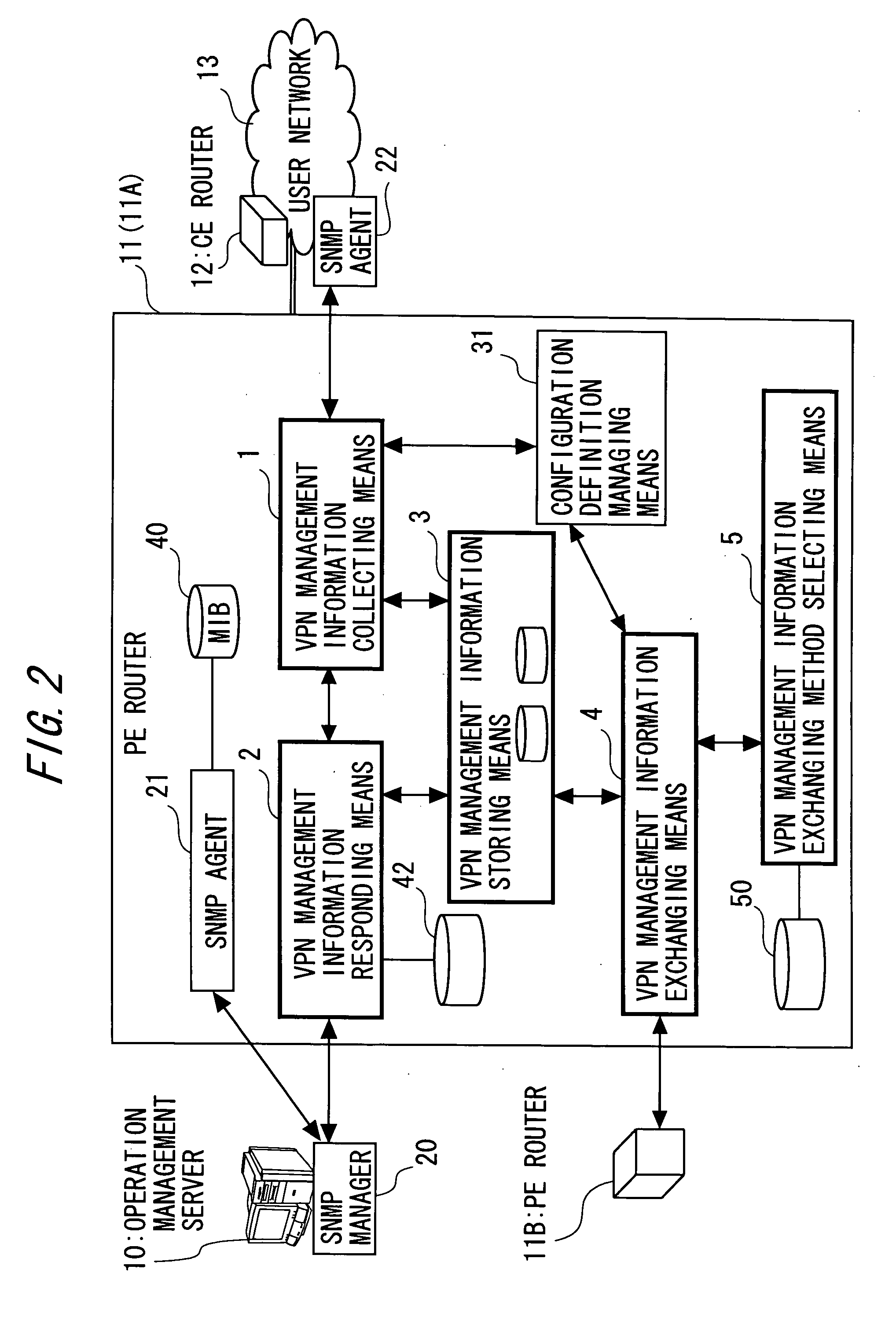
[0085] A first embodiment of the present invention is described with reference to FIGS. 3 to 5. FIG. 3 is a system configuration diagram of an information system according to the first embodiment of the present invention. Basically, the information system includes similar constituent elements to the constituent elements shown in FIG. 2 showing the above-described principle of the invention. Hence, in this embodiment, the same reference numerals as those in FIG. 2 are given to the same constituent elements as those in FIG. 2, and description thereof is omitted.

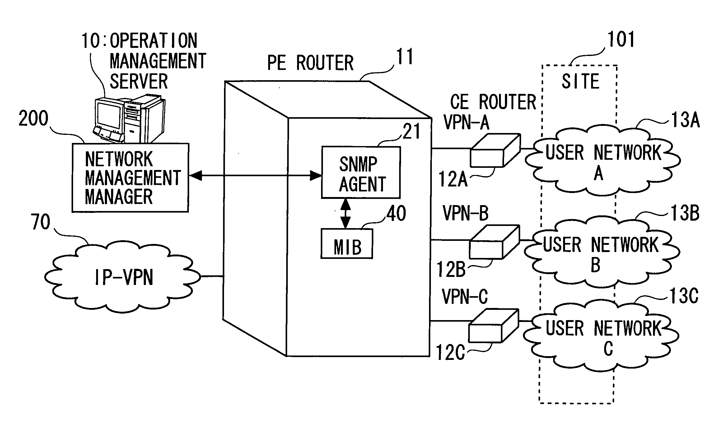
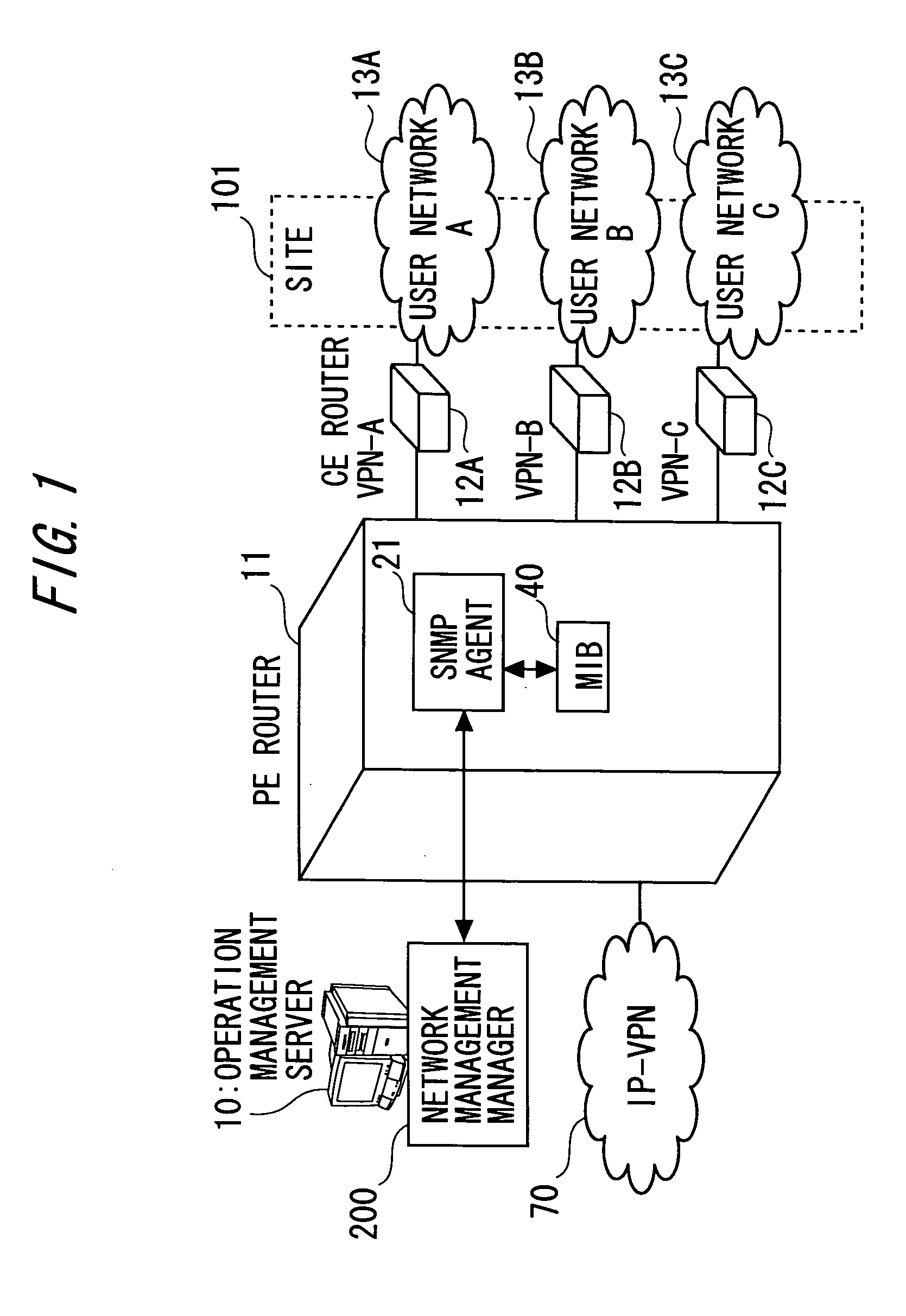
[0086] Note that, in FIG. 3, three networks 13A, 13B, and 13C are shown as the user networks. In this embodiment, it is assumed that the user networks 13A, 13B, and 13C are connected to networks of the other sites by VPNs which are a VPN-A, a VPN-B, and a VPN-C.

[0087] Moreover, in this embodiment, CE routers 12A, 12B, and 12C are provided in the user networks 13A, 13B, and 13C, respectively. Furthermore, SNMP agents 22A, 22B,...

second embodiment

[0108] A second embodiment of the present invention will be described with reference to FIGS. 6 to 9. Described in the first embodiment is an example of the information system where the operation management server 10 designates the VPN by using the virtual IP address to collect the network management information such as MIBs or Traps from the PE routers 11. In this embodiment, description is made of an example of an information system where the plural PE routers 11 exchange the MIB information with each other. Other constituent elements and operations of the information system are the same as in the first embodiment. Thus, the same reference numerals are given to the same constituent elements as those in the first embodiment and their description is omitted here.

[0109]FIG. 6 is a system configuration diagram of the information system according to this embodiment. In FIG. 6, a plurality of networks of two sites 101 and 102 are connected to each other through an IP-VPN 70. In the exa...

third embodiment

[0125] A third embodiment of the present invention will be described with reference to FIGS. 10 and 11. Described in the second embodiment is an example where the plural PE routers 11 exchange the MIB information with each other. In this embodiment, description is made of an information system having a function of enabling the user to set communication unit when the plural PE routers 11 exchange the MIB information with each other. Other constituent elements and operations of the information system are the same as in the first or second embodiment. Thus, the same reference numerals are given to the same constituent elements as those in the first or second embodiment and their description is omitted here.

[0126]FIG. 10 is a system configuration diagram of the information system of this embodiment. Users of networks which utilize the VPNs can select in advance unit of communication for exchanging the MIBs, which is performed in VPN management information exchanging unit 4X, 4Y, and th...


PUM


Abstract

To collectively manage user networks connected to a virtual private network (VPN) without such time and effort necessary for an operation management server to be ready for an expansion MIB for each of vendors. Provided is a network management system, including: a first edge router, an operation management server and a second edge router which connects to the first edge router, the second edge router being included in the network constituted for each of the user groups, wherein the first edge router includes: collecting unit for collecting management information regarding constituent elements of the network constituted for each of the user groups from the second edge router on the network constituted for each of the user groups, unit for storing the management information in correspondence with the virtual private network for each of the user groups, and unit for returning the management information when receiving, from the operation management server, a request for the management information brought in correspondence with the virtual private network for each of the user groups, and the operation management server includes requesting unit for designating the virtual private network for each of the user groups and requesting the first edge router to return the management information regarding the constituent elements of the network constituted for each user group connected to the virtual private network.

Description

BACKGROUND OF THE INVENTION [0001] The present invention relates to a management technology for a user network connected to a virtual private network (VPN). [0002] In recent years, when an enterprise connects Local Area Networks (LANs) of its business sites such as headquarters and branch offices to one another, instead of private lines provided by a telecommunication carrier and a Wide Area Network (WAN) using frame relays, Virtual Private Network (VPN) services using the Internet have been utilized. [0003] The most widespread protocol for managing the networks for use in these services is the Simple Network Management Protocol (SNMP) defined by Request For Comment (RFC) 1157 managed by the Internet Engineering Task Force (IETF). The SNMP is composed of SNMP agents which reside in network instruments to be managed and an SNMP manager which manages the networks. [0004] Each SNMP agent manages information of the network instrument as a Management Information Base (MIB). The MIB is an...

Claims


Application Information

Patent Timeline
IPC IPC(8): H04L12/24H04L12/70H04L12/28H04L12/46
CPCH04L12/4675H04L41/046H04L41/0213H04L41/40
Inventor ITO, YUJINAKAMOTO, NORIOMUKAIHARA, MASATAKAKURANARI, SHINICHI
Owner FUJITSU LTD
Features
  • Generate Ideas
  • Intellectual Property
  • Life Sciences
  • Materials
  • Tech Scout
  • Unparalleled Data Quality
  • Higher Quality Content
  • 60% Fewer Hallucinations
Learn More