Surface treatment and surface scanning

a surface treatment and scanning technology, applied in the field of surface treatment devices and surface scanning devices, can solve the problems of heat up of the probe, contaminated tip of the probe, wear, etc., and achieve the effect of effective sharpening of the prob

Inactive Publication Date: 2005-12-22
IBM CORP
View PDF2 Cites 1 Cited by
  • Summary
  • Abstract
  • Description
  • Claims
  • Application Information

AI Technical Summary

Benefits of technology

[0012] In an advantageous embodiment the sharpening location comprises a flank with an edge being formed such, that during a movement of the tip in direction towards the flank first a generated surface of the tip is in contact with the edge before the apex contacts the edge. In that way the geometrical properties of the sharpening location are such, that the wear at the generated surface of the tip is larger, when the tip is moved towards the flank so far that also the apex is moved across the edge, than the wear on the apex of the tip. This results in an effective sharpening of the probe.

Problems solved by technology

The heater cantilever is supplied with an amount of electrical energy, which causes the probe to heat up to a temperature that is not high enough to soften the polymer layer as is necessary for writing.
However it has been shown that during the operation of the surface treatment or surface scanning devices the tip of their probe may get contaminated or may be subject to wear.
Accordingly, it is a challenge to provide a surface treatment device, a surface scanning device, a method of operating a surface treatment device and a method of operating a surface scanning device which enables a precise and long-lasting operation.

Method used


Image

  • Surface treatment and surface scanning
  • Surface treatment and surface scanning
  • Surface treatment and surface scanning

Examples


Embodiment Construction

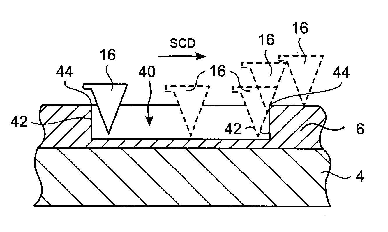
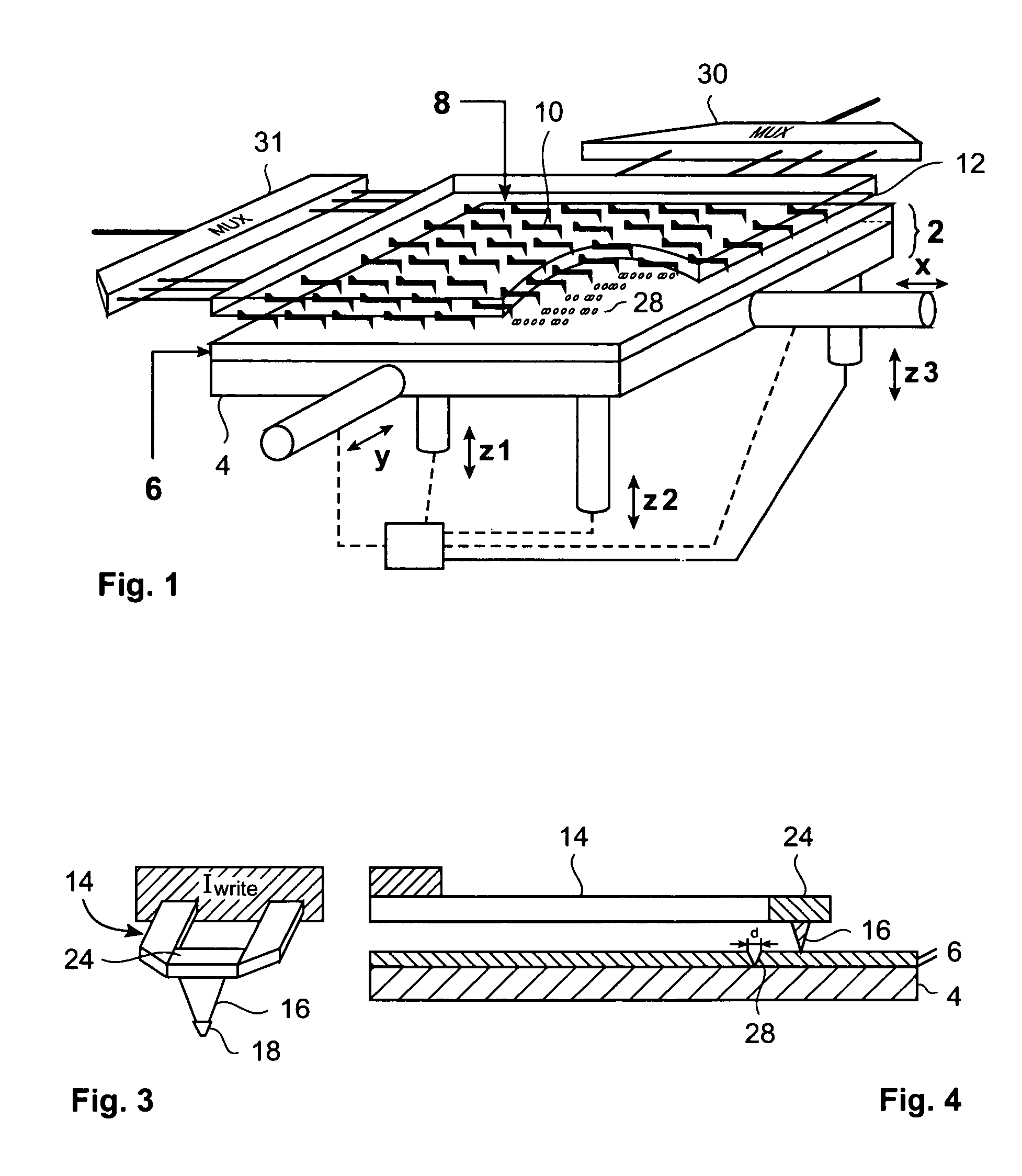
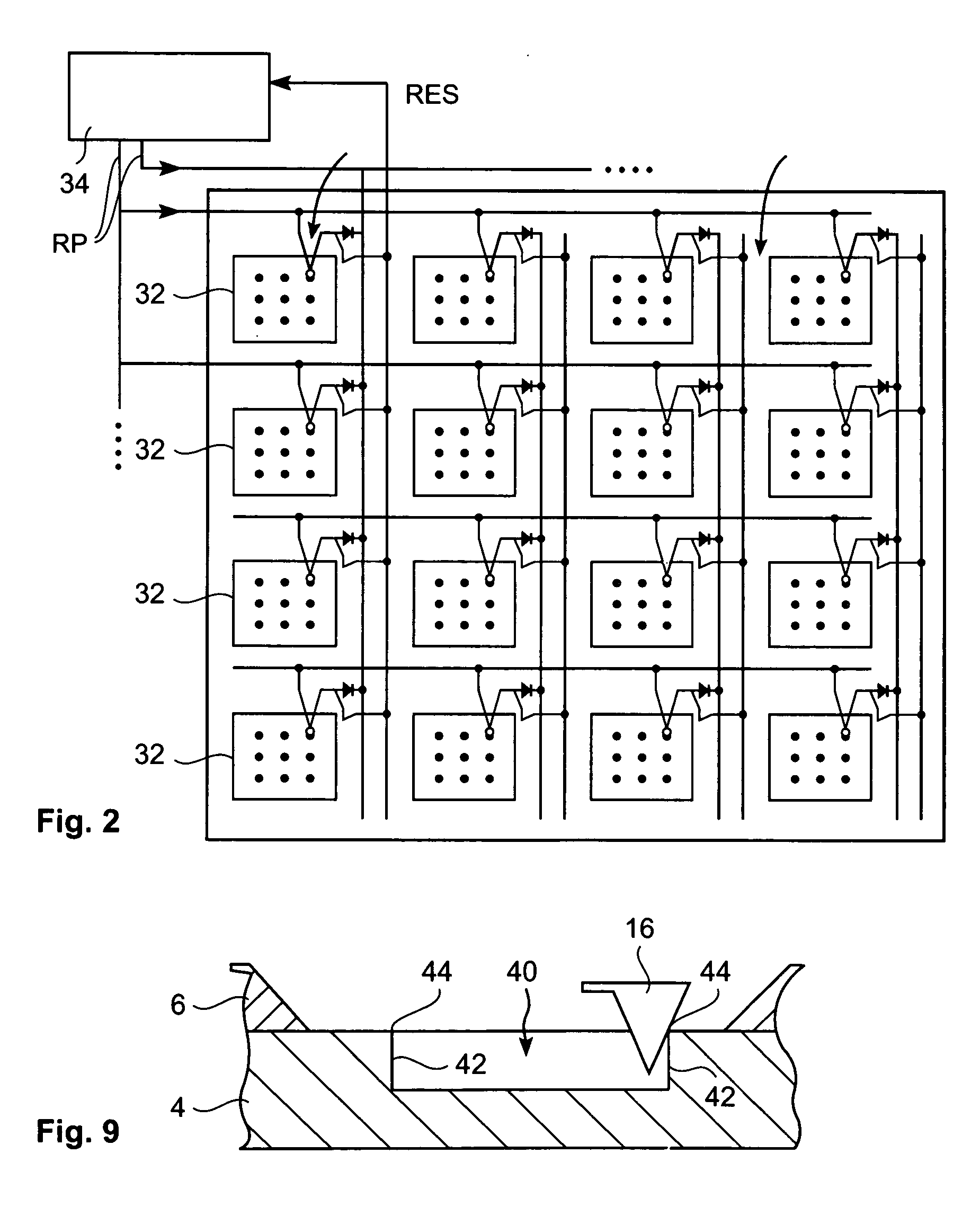
[0054] The invention provides a surface treatment device, a surface scanning device, a method of operating a surface treatment device and a method of operating a surface scanning device which enable a precise and long-lasting operation. An example of a surface treatment device, comprises a medium with a surface, at least one probe designed for altering the surface of said medium and comprising a conically-shaped tip with an apex radius smaller than 100 nm. An area within the medium comprises at least one sharpening location for sharpening the tip mechanically. The material of the medium with the surface is not limited. Preferentially it comprises a substrate and a polymer layer which then faces the probe. Also the way the probe alters the surface of the medium is not limited, it may for example alter the medium thermomechanically, thermally or only by mechanical forces. The surface treatment device further comprises a drive for moving the medium and / or the probe relatively to each o...


PUM

PropertyMeasurementUnit
radiusaaaaaaaaaa
voltageaaaaaaaaaa
apex radiusaaaaaaaaaa

Abstract

Provides surface treatment devices, surface scanning devices, methods of operating a surface treatment device and methods of operating a surface scanning device. An area within a medium comprises at least one sharpening location for sharpening a tip of a probe mechanically. The tip is conically shaped with a radius of an apex smaller than 100 nm. In the case of the surface treatment device the probe is designed for altering the surface of the medium. In the case of the surface scanning device the probe is designed for scanning the medium. The sharpening location is suited for sharpening the tip mechanically. For that purpose the probe and the medium are being moved relative to each other such that the tip is located in the sharpening location. Then the probe and / or the medium are moved relative to each other such, that the tip is mechanically sharpened.

Description

TECHNICAL FIELD [0001] The present invention relates to a surface treatment device, a surface scanning device, a method for operating a surface treatment device and a method for operating a surface scanning device. BACKGROUND OF THE INVENTION [0002] Different concepts for scanning surfaces in particular with a resolution in the nanoscale range, have been proposed. Also concepts for treating surfaces, in particular in the nanoscale range, have been proposed recently. [0003] An example of the concept for surface scanning is a scanning tunneling microscope, which is disclosed in the applicant's U.S. Pat. No. 4,343,993. The scanning tunneling microscope comprises a conductive tip that serves as a scanning electrode. The conductive tip is arranged movably in respect to a conductive sample. During the operation of the scanning tunneling microscope the tip is moved across a surface of the conductive sample in close relationship to the conductive sample. The distance between the surface of ...

Claims


Application Information

Patent Timeline
Patent Type & Authority Applications(United States)
IPC IPC(8): B29C37/02G01Q10/00G01Q70/16G01Q80/00G11B9/00
CPCB82Y10/00G01Q70/06G11B9/1481G11B9/1454G01Q80/00
Inventor BINNIG, GERD K.HAEBERLE, WALTERWIESMANN, DOROTHEA W.
Owner IBM CORP
Why Eureka
Try Eureka