Magnetic detecting element having a self-pinned layer

US20050280955A1Active Publication Date: 2005-12-22TDK CORPARATION

Image

  • Magnetic detecting element having a self-pinned layer
  • Magnetic detecting element having a self-pinned layer
  • Magnetic detecting element having a self-pinned layer

Examples


Embodiment Construction

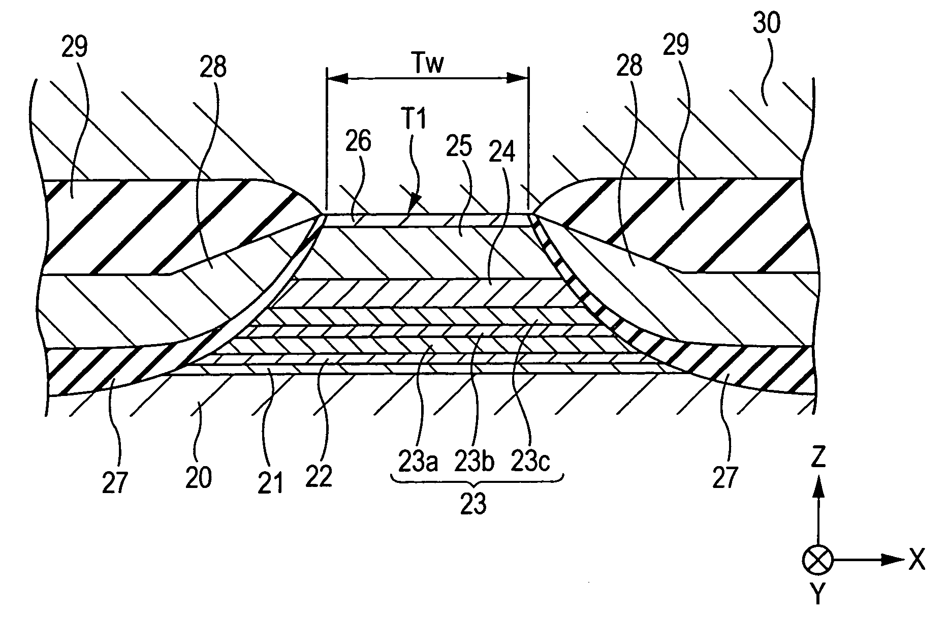
[0074]FIG. 1 is a sectional view of a magnetic detecting element according to a first embodiment of the present invention, viewed from the side surface opposing the recording medium, and FIG. 4 is a fragmentary schematic diagram of the magnetic detecting element shown in FIG. 1.

[0075] The magnetic detecting element shown in FIGS. 1 and 4 has a multilayer composite T1 on a lower shield layer 20 made of a magnetic material.

[0076] The multilayer composite T1 is formed by depositing a seed layer 21, a magnetostriction-enhancing layer 22, a pinned magnetic layer 23, a nonmagnetic material layer 24, a free magnetic layer 25, and a protective layer 26 in that order on the shield layer 20.

[0077] The seed layer 21 is formed of a NiFe alloy, a NiFeCr alloy, Cr, Ta, or the like. For example, the seed layer 21 is formed of 60 atomic percent of Ni0.8Fe0.2 and 40 atomic percent of Cr to a thickness of 35 to 60 ā„«.

[0078] The seed layer 21 helps the magnetostriction-enhancing layer 22, which is ...


PUM


Abstract

A CPP magnetic detecting element having a pinned magnetic layer whose magnetization is fixed by its uniaxial anisotropy in a structure that CIP magnetic detecting elements do not allow. In the CPP magnetic detecting element, the upper and lower surfaces of a pinned magnetic layer having an artificial ferrimagnetic structure are disposed between a magnetostriction-enhancing layer made of a nonmagnetic metal and a nonmagnetic material layer having a higher lattice constant than Cu. CPP magnetic detecting elements allow this structure without reducing the variation in resistance per unit area ΔR·A. Thus, the magnetostriction coefficient of the pinned magnetic layer can be increased from above and below, thereby more firmly fixing the magnetization of the pinned magnetic layer.

Description

BACKGROUND OF THE INVENTION [0001] 1. Field of the Invention [0002] The present invention relates to CPP (current-perpendicular-to-the-plane) magnetic detecting elements, and particularly to a CPP magnetic detecting element having a structure which CIP (current-in-the-plane) magnetic detecting elements do not allow and in which the magnetization of a pinned magnetic layer is more firmly fixed by the uniaxial anisotropy of the pinned magnetic layer. [0003] 2. Description of the Related Art [0004] A magnetic detecting element having a multilayer composite including a free magnetic layer, a nonmagnetic material layer, and a pinned magnetic layer may be of a CIP type or a CPP type, according to the direction of current flowing in the multilayer composite. [0005] In a CIP magnetic detecting element, current flows in a direction parallel to the surfaces of the layers of the multilayer composite. In a CPP magnetic detecting element, current flows in the direction perpendicular to the surfa...

Claims


Application Information

Patent Timeline
22 Dec 2005
Publication
US20050280955A1
IPC
G01R33/09; G11B5/127; G11B5/33; G11B5/39
CPC
B82Y10/00; B82Y25/00; G11B2005/3996; G11B5/3932; G01R33/093
Inventors
HASEGAWA, NAOYA; SAITO, MASAMICHI