Implantable biostructure comprising an osteoconductive member and an osteoinductive material

a biostructure and osteoinductive technology, applied in the field of osteoinductive materials, can solve the problems of conflict or mismatch between dimensional scales, only applicable to osteoinductive substances, and not being able to meet both requirements simultaneously

Inactive Publication Date: 2005-12-22
THERICS
View PDF3 Cites 75 Cited by
  • Summary
  • Abstract
  • Description
  • Claims
  • Application Information

AI Technical Summary

Benefits of technology

[0013] The biostructure includes a porous matrix, which may be osteoconductive and may comprise a ceramic such as tricalcium phosphate. In some embodiments, the matrix may comprise polymer or may comprise both ceramic and polymer. The matrix also may comprise one or more channels, recesses or internal region(s), whose size is larger than the size of pores, with the channels, recesses or internal region(s) being suitably dimensioned so as to contain osteoinductive material. The biostructure also may comprise particles of osteoinductive material such as demineralized bone matrix, which may exist in the form of particles greater than a certain minimum size. The particles of demineralized bone matrix may be contained in the interior of the biostructure, or may be attached to the exterior of the biostructure, or both. The biostructure may further comprise another material which holds the osteoinductive particles in place. The biostructure can have a shape suitable for use as any of a variety of bone replacements and can be suitable to be carved at the point of use and suitable to wick bodily fluids. The invention also includes methods of manufacturing such a biostructure. The particles of demineralized bone matrix may be added at a stage later than the manufacturing of the matrix. The biostructure may assembled from more than one piece.

Problems solved by technology

However, this approach has only been applicable to osteoinductive substances which are liquids.
This has involved an inherent conflict or mismatch of dimensional scales.
With a conventional biostructure which is of uniform architecture, it has not been possible to satisfy both of these requirements simultaneously.
This conflict in terms of desired pore size has worked against the optimum use of demineralized bone matrix, which is an excellent osteoinductive material, in rigid osteoconductive structures.

Method used


Image

  • Implantable biostructure comprising an osteoconductive member and an osteoinductive material
  • Implantable biostructure comprising an osteoconductive member and an osteoinductive material
  • Implantable biostructure comprising an osteoconductive member and an osteoinductive material

Examples


Embodiment Construction

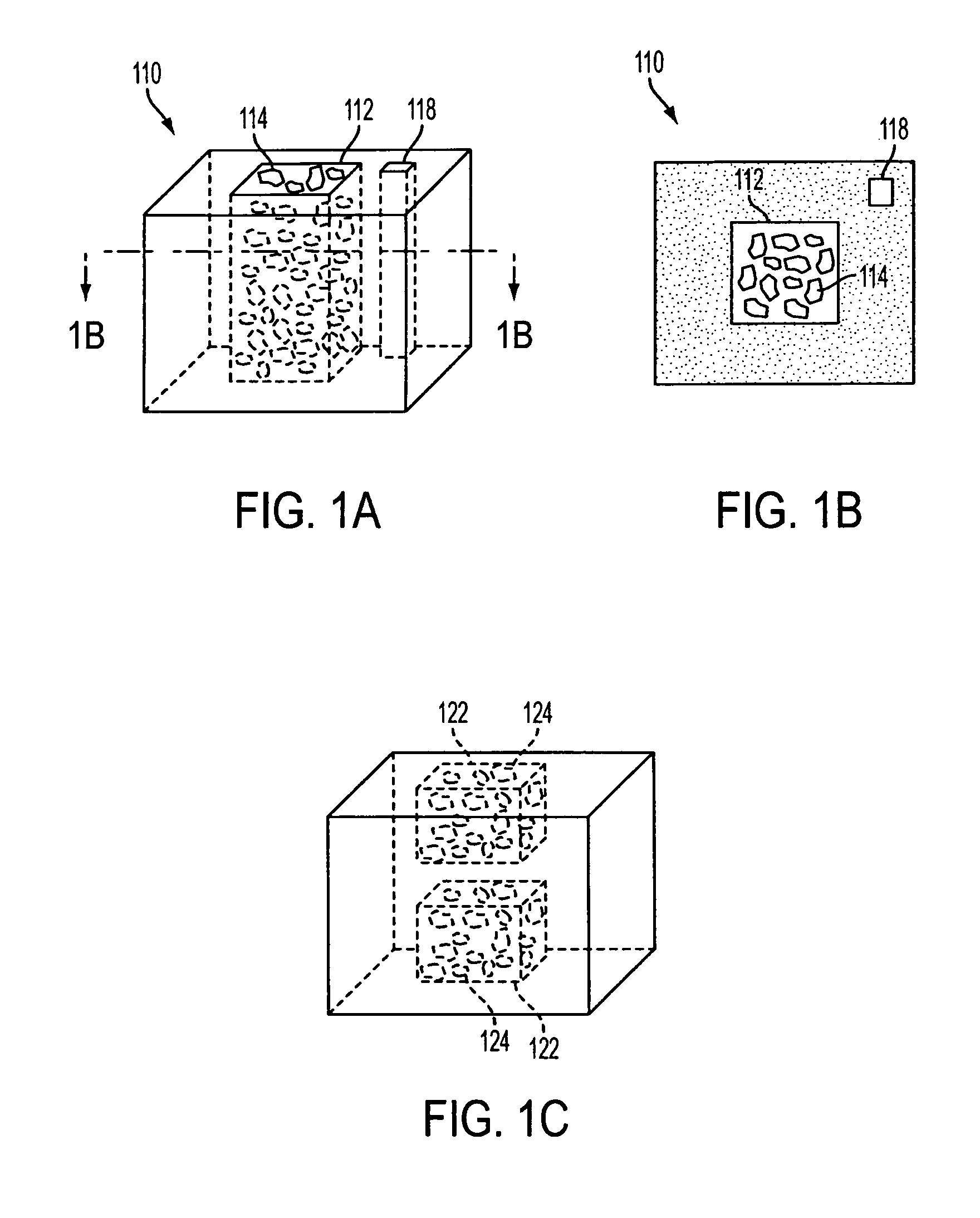
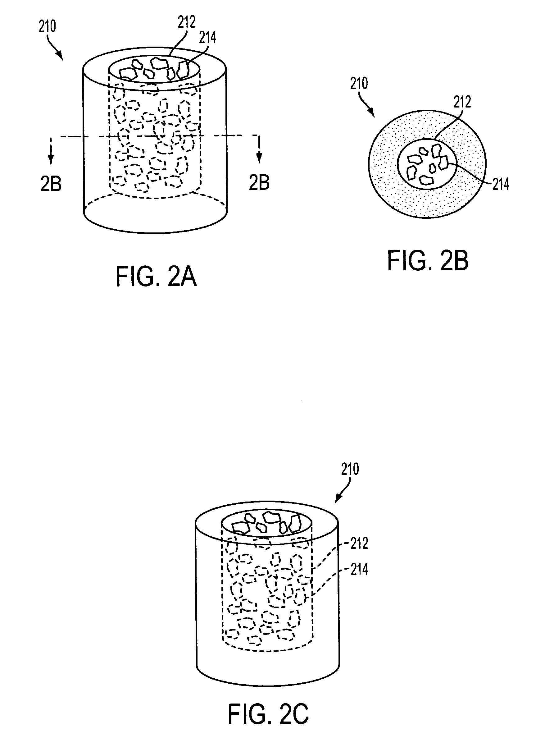
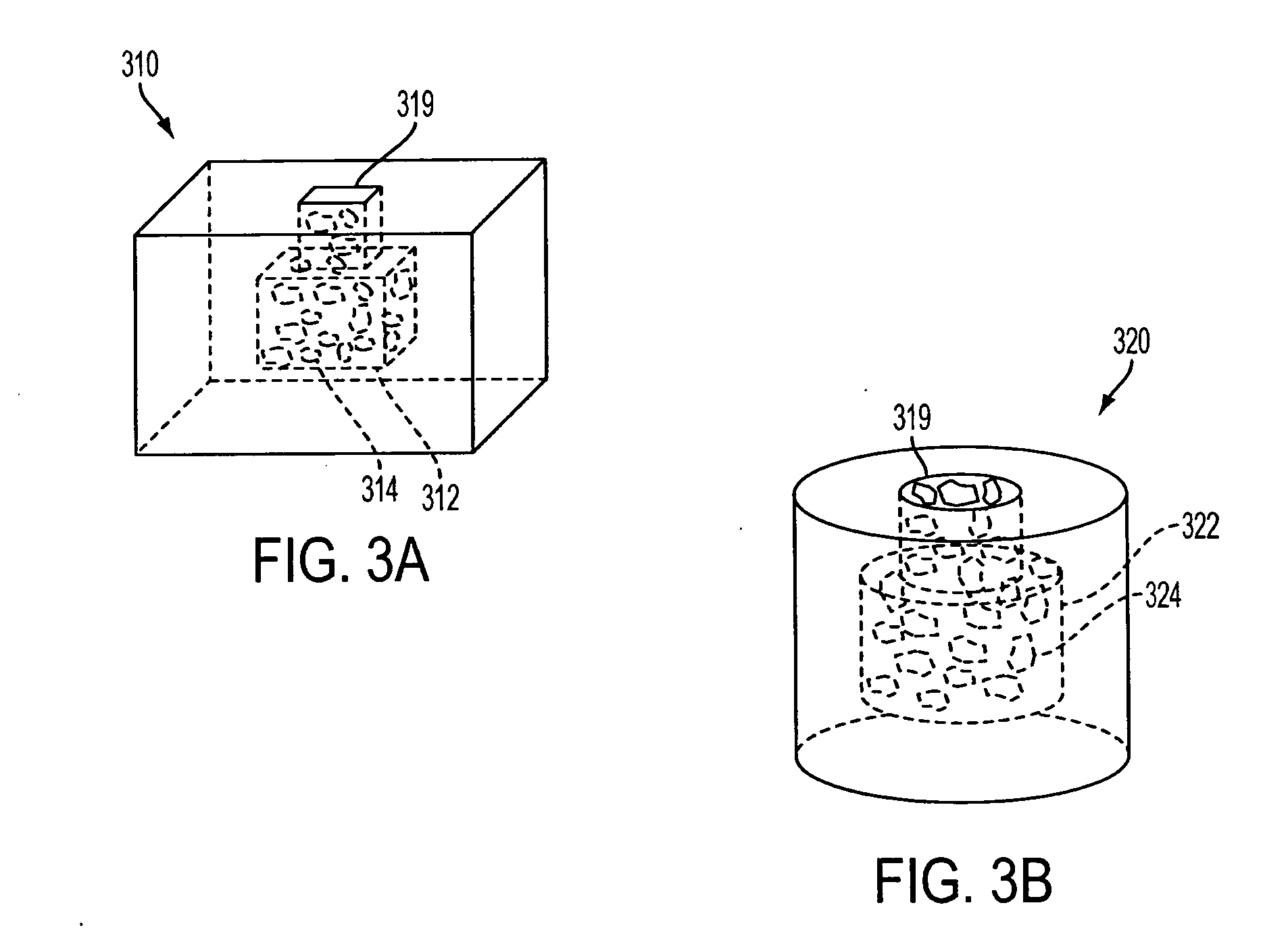
[0023] The invention includes a biostructure having an overall shape. The biostructure may, first of all, comprise a matrix which is porous. The pores may be characterized by pore sizes which may be in the range of approximately 1 micrometer to approximately 1000 micrometers. In certain embodiments, the pore size distribution has a peak between 50 and 100 micrometers. In one embodiment the matrix may comprise particles which are partially joined directly to each other but still leave some space between themselves in the form of pores. In another embodiment the matrix may comprise particles which are joined to each other by another substance(s). In any embodiment the matrix may be osteoconductive, such as by virtue of the geometry and / or composition of the matrix.

[0024] The matrix may further include macroscopic channels which are suitable to be occupied by particles of DBM. The macroscopic channels may have cross-sectional dimensions which, first of all, are greater than approximat...


PUM

PropertyMeasurementUnit
pore sizesaaaaaaaaaa
sizeaaaaaaaaaa

Abstract

The present invention is directed to a biostructure comprising an osteoconductive member and an osteoinductive material. The osteoinductive material may be located within a cavity in the osteoconductive material. In one aspect of the invention the osteoinductive material is demineralized bone matrix and the osteoconductive member comprises tricalcium phosphate.

Description

[0001] This application claims priority under 35 U.S.C. § 119(e) to U.S. Provisional Application 60 / 569,921, filed on May 10, 2004, and U.S. Provisional Application 60 / 583,670, filed on Jun. 28, 2004, both of which are incorporated by reference in their entirety.BACKGROUND OF THE INVENTION [0002] 1. Field of the Invention [0003] The invention pertains to implants for the healing and regeneration of bone and more particularly to an osteoconductive matrix having selective deposits of demineralized bone in channels, passageways, cavities and lumens of the matrix. [0004] 2. Description of the Related Art [0005] Implants to encourage the regeneration and healing of bone have come into increasing use. Among the materials used have been autograft (the patient's own bone), allograft (bone from deceased human donors), and synthetic materials such as members of the calcium phosphate family. [0006] Synthetic ceramic materials have been shown to be osteoconductive, i.e., able to conduct the ing...

Claims


Application Information

Patent Timeline
Patent Type & Authority Applications(United States)
IPC IPC(8): A61F2/00A61F2/02A61F2/28A61F2/30A61K31/724A61L27/36A61L27/42A61L27/56
CPCA61F2/28A61L27/56A61F2/30767A61F2002/2835A61F2002/30059A61F2002/30062A61F2002/30153A61F2002/30154A61F2002/30179A61F2002/30224A61F2002/30225A61F2002/30235A61F2002/30261A61F2002/30263A61F2002/30271A61F2002/30604A61F2002/30677A61F2002/30772A61F2002/30785A61F2002/30795A61F2002/30807A61F2002/30813A61F2002/30815A61F2002/30822A61F2002/30957A61F2002/30985A61F2210/0004A61F2230/0019A61F2230/0021A61F2230/0058A61F2230/0069A61F2230/0082A61F2230/0084A61F2310/00293A61K31/724A61L27/3608A61L27/365A61L27/425A61F2/30744A61F2002/30593
Inventor MCGLOHORN, JONATHANSAINI, SUNILCARUSO, ANDREA B.WEST, THOMAS GEORGEMATERNA, PETER A.SHAROBIEM, JOHNBRADBURY, THOMAS J.
Owner THERICS
Why Eureka
Try Eureka