Catheter assembly

a technology of catheter and assembly, which is applied in the field of catheter, can solve the problems of inability to effectively operate by one person, inability to perform wire exchange, and inability to direct longitudinal force along the path of guidewire, etc., and achieve the effect of improving columnar strength

Active Publication Date: 2005-12-22
WL GORE & ASSOC INC
View PDF23 Cites 152 Cited by
  • Summary
  • Abstract
  • Description
  • Claims
  • Application Information

AI Technical Summary

Benefits of technology

[0013] The proximal section of the catheter also includes a guidewire receiving lumen. The guidewire receiving lumen may extend from the distal end of the proximal section to a point distal of the proximal end, or the guidewire receiving lumen may extend from the distal end of the proximal section to the proximal end thereof. The guidewire receiving lumen includes at least one proximal guidewire exit port located proximally from the distal end of the proximal section. The reinforcing tubular member extends to a point distal of the proximal guidewire exit port, and has an outer diameter equal to about the inner diameter of the delivery lumen for at least a portion of the reinforcing tubular member that extends distal to the proximal guidewire exit port. By extending the reinforcing tubular member distal to the guidewire exit port in this manner, the catheter will have improved columnar strength (i.e. it will resist buckling while being advanced, or pushed, toward the desired treatment site) and pushability. The guidewire receiving lumen and the delivery lumen should be in a parallel relationship. This allows for the reinforcing tubular member to extend distal to the proximal guidewire exit port, while maintaining an outer diameter equal to about the inner diameter of the delivery lumen to provide structural support about the circumference of the lumen distal to the proximal guidewire exit port.

Problems solved by technology

However, these systems require the use of a long guidewire (e.g., 300 cm in length) and cannot be effectively operated by one person.
However, because the entire length of the RX catheter does not slide over the guidewire, the direct transmission of longitudinal force along the path of the guidewire may be compromised, and wire exchange can not be performed once the proximal catheter guidewire port is advanced into the patient.
Another problem with the design of RX catheters is that, compared to traditional OTW catheters, it results in catheters which have inferior pushability and also tend to buckle and / or kink—especially at or near the proximal (or rapid-exchange) guide wire exit port.
A further problem with conventional balloon catheters for intravascular procedures, such as angioplasty and stent delivery, is such catheters frequently have stiff proximal sections to facilitate advancement of the catheter within the patient's body lumen and relatively flexible distal shaft sections to facilitate passage through tortuous anatomy such as distal coronary and neurological arteries without damage to the luminal wall.

Method used


Image

  • Catheter assembly
  • Catheter assembly
  • Catheter assembly

Examples


Embodiment Construction

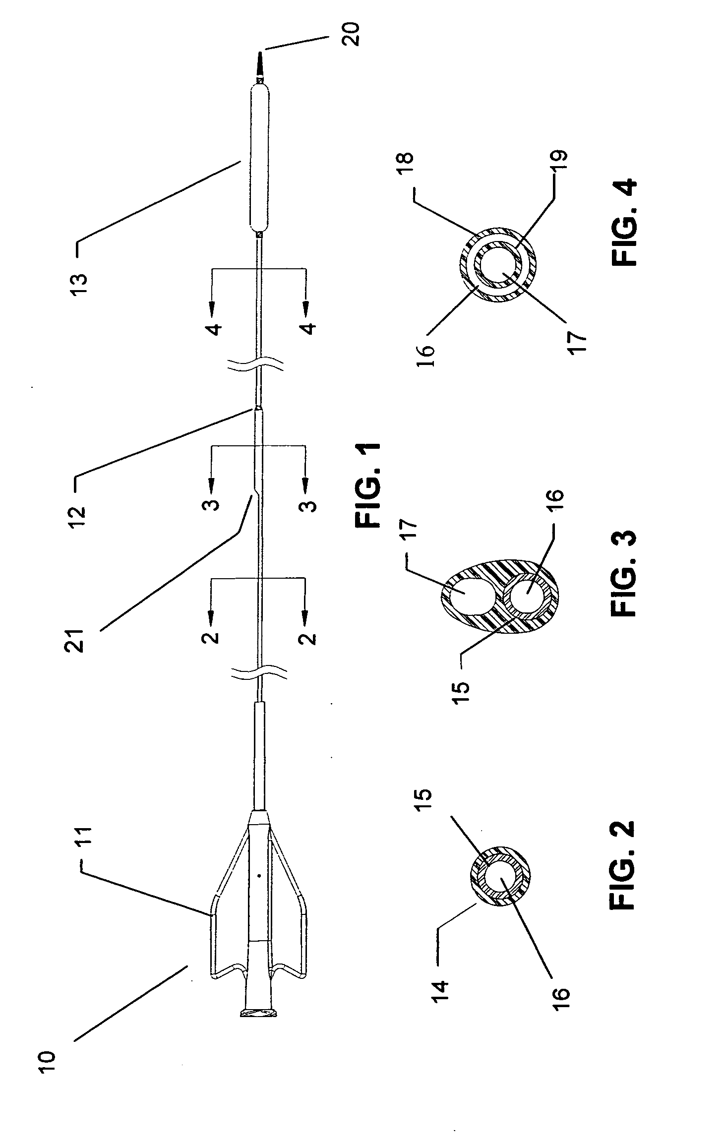
[0027] The invention may best be understood with reference to the Figures wherein certain preferred embodiments are set forth in detail.

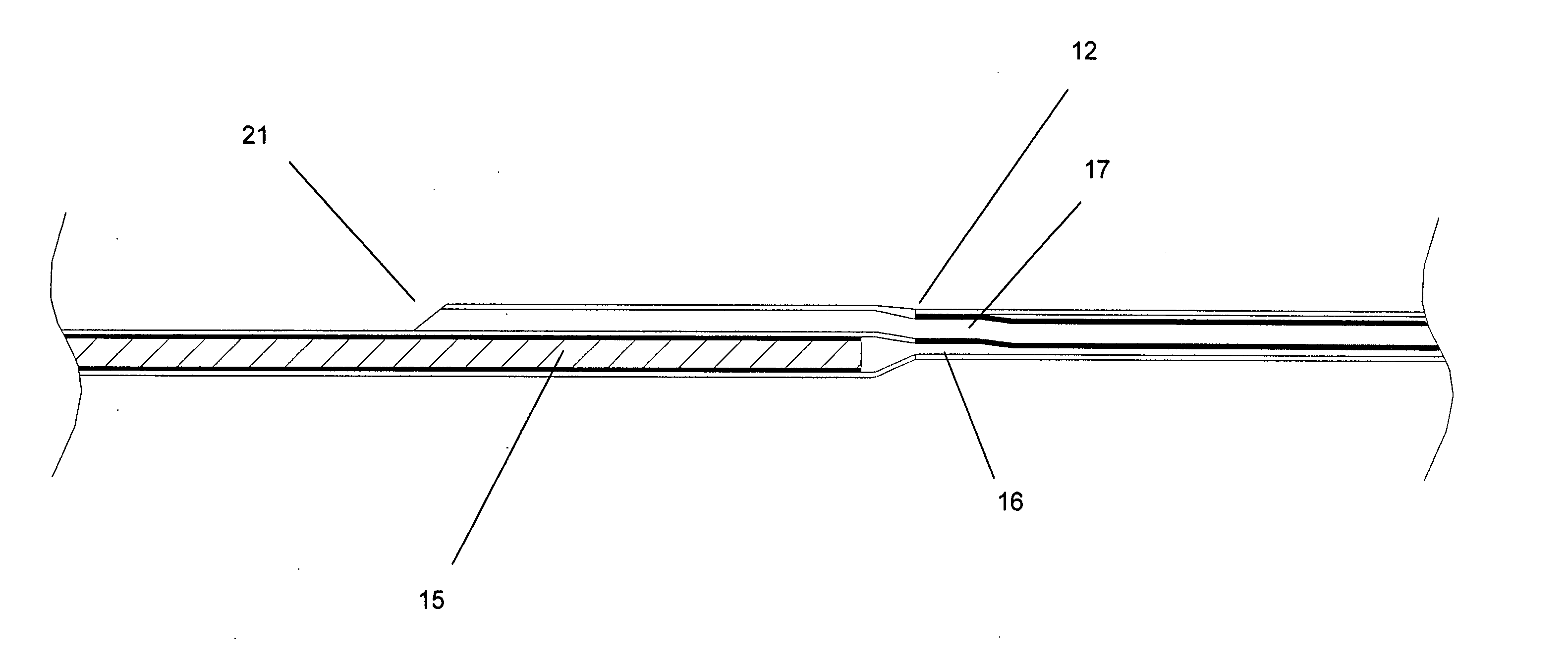
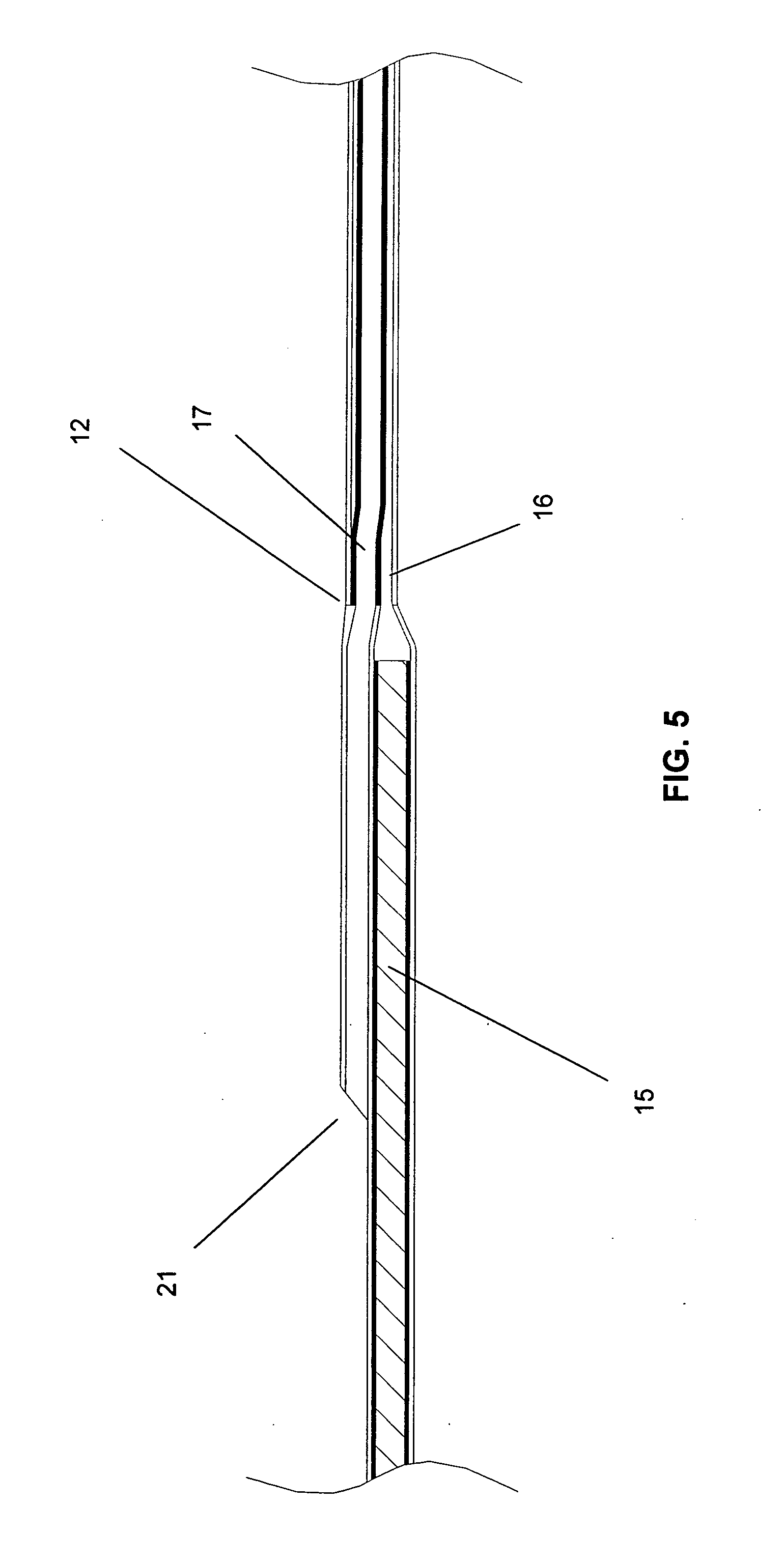
[0028] Turning to FIG. 1 there is shown a rapid-exchange type balloon catheter 10. Typically located on the proximal end of such a catheter is hub assembly 11. As can be seen catheter 10 includes a proximal section and a distal section in this case joined in abutting relationship at joint 12. The proximal section and distal section can be joined in any suitable manner, such as adhesively joined, fused, welded, etc. In an aspect of the invention the proximal and distal sections are butt welded, glued, etc. together so as to form a smooth joint without one section overlapping the other, and without a transition piece, such as a hollow tube, fitted over each piece. As shown in FIG. 2, proximal section includes an outer wall material 14 (such as a plastic material, or other suitable material) and reinforcing tubular member 15 supporting the outer wall ...


PUM

PropertyMeasurementUnit
lengthaaaaaaaaaa
lengthaaaaaaaaaa
lengthaaaaaaaaaa

Abstract

Catheter having a proximal section and a distal section. The proximal section having at least a delivery lumen and a guidewire receiving lumen, the guidewire receiving lumen having a proximal guidewire exit port at a location proximal of the distal end of the proximal section. A reinforcing tubular member located in the proximal section delivery lumen extending from substantially the proximal end of the proximal section to a point distal to the proximal guidewire exit port, wherein the reinforcing tubular member transitions from relatively rigid to relatively more flexible from a proximal point to a distal point thereon and has an outer diameter equal to about the inner diameter of the delivery lumen for at least a portion of the reinforcing tubular member that extends distal to the proximal guidewire exit port. The distal section having at least a delivery lumen and a guidewire receiving lumen.

Description

FIELD OF THE INVENTION [0001] The present invention relates to catheters having at least a guide wire lumen and a delivery lumen. BACKGROUND OF THE INVENTION [0002] A variety of different therapies can be delivered within the human body by catheter devices. Therapeutic devices such as dilatation balloons, stents, and embolic filters, and therapeutic agents such as drugs and radiation sources, may be positioned at or near the distal end of the catheter for delivery to a desired site within the body. [0003] The prior art discloses numerous examples of intravascular catheters. Such catheters have found particular utility for procedures such as angioplasty and stent deployment. Of particular interest recently is improving catheters for use in percutaneous transluminal coronary angioplasty (PTCA) procedures. In typical PTCA procedures a guiding catheter is advanced in the patient's vasculature until the distal tip of the guiding catheter is seated in the ostium of a desired coronary arte...

Claims


Application Information

Patent Timeline
Patent Type & Authority Applications(United States)
IPC IPC(8): A61F2/958A61M25/00
CPCA61M25/0023A61M25/0029A61M25/0045A61M2025/0183A61M25/10A61M2025/0037A61M2025/0039A61M25/0054
Inventor MANN, JAMES W.ESKAROS, SHERIF A.LAFFERTY, ERIC C.MESSICK, DAVID J.
Owner WL GORE & ASSOC INC
Why Eureka
Try Eureka