
Baby bouncer actuator and related systems

a technology for a baby bouncer and a related system, which is applied in the field of baby bouncer actuators, can solve the problems that fixed speed actuators (e.g., motorized swing actuators) have not been used effectively with baby bouncers

Inactive Publication Date: 2005-12-29
JETTA
View PDF4 Cites 52 Cited by
  • Summary
  • Abstract
  • Description
  • Claims
  • Application Information

AI Technical Summary

Benefits of technology

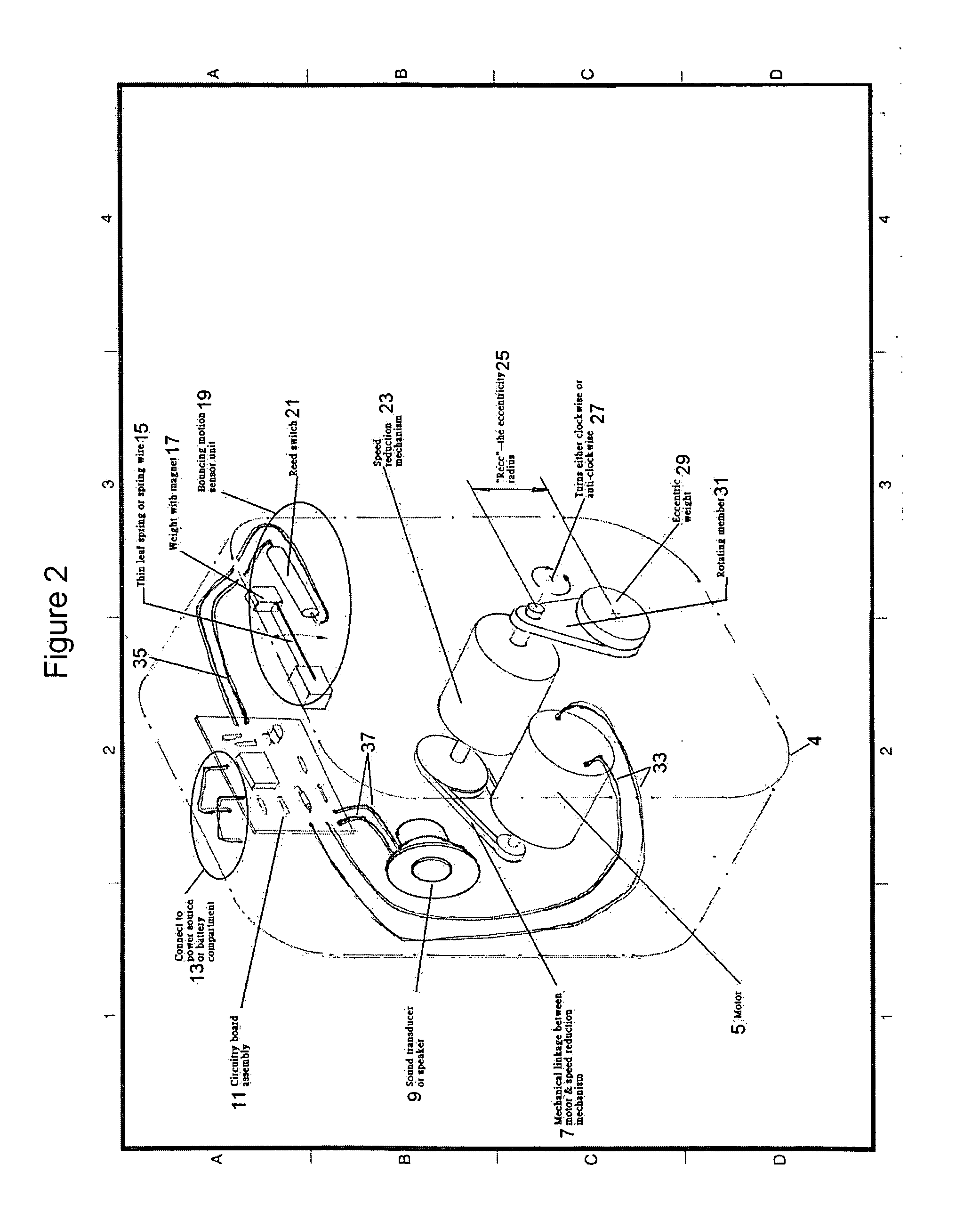
[0010] A microprocessor-controlled actuator of the invention comprises: (a) a housing adapted to engage and bounce a baby bouncer system; (b) a motion sensor which can generate signals corresponding to baby bouncer system forces and which is enclosed within and supported by the housing; (c) a microprocessor based control system which can detect and store the motion sensor signals and which is enclosed within and supported by the housing; (d) a DC electric motor which (i) is connectable to a power source, (ii) is in electrical communication with the microprocessor based control system, (iii) during operation receives a supply voltage at a level which is regulated by the microprocessor based control system, and (iv) is enclosed within and supported by the housing; (e) a speed reduction mechanism which comprises an axial shaft connected for rotation to and driven by the DC electric motor and which is enclosed within and supported by the housing; (f) a rotatable eccentric weight which is mounted coaxially on the speed reduction mechanism axial shaft for rotational motion to generate centrifugal force and which is enclosed within and supported by the housing; wherein the microprocessor based control system is calibrated to maintain the DC electric motor supply voltage level at a value which is optimized to maintain baby bouncer system bouncing at a soothing frequency, e.g., about 1 to 2 Hz.
[0011] The speed reduction ratio of the speed reduction mechanism is preferably set such that the rotational speed of the ac

Problems solved by technology

Currently available fixed speed actuators (e.g., motorized swing actuators) have not been employed effectively with baby bouncers to either affect a natural bouncing motion or achieve optimum bouncer frequencies.

Method used


Image

  • Baby bouncer actuator and related systems
  • Baby bouncer actuator and related systems
  • Baby bouncer actuator and related systems

Examples


Embodiment Construction

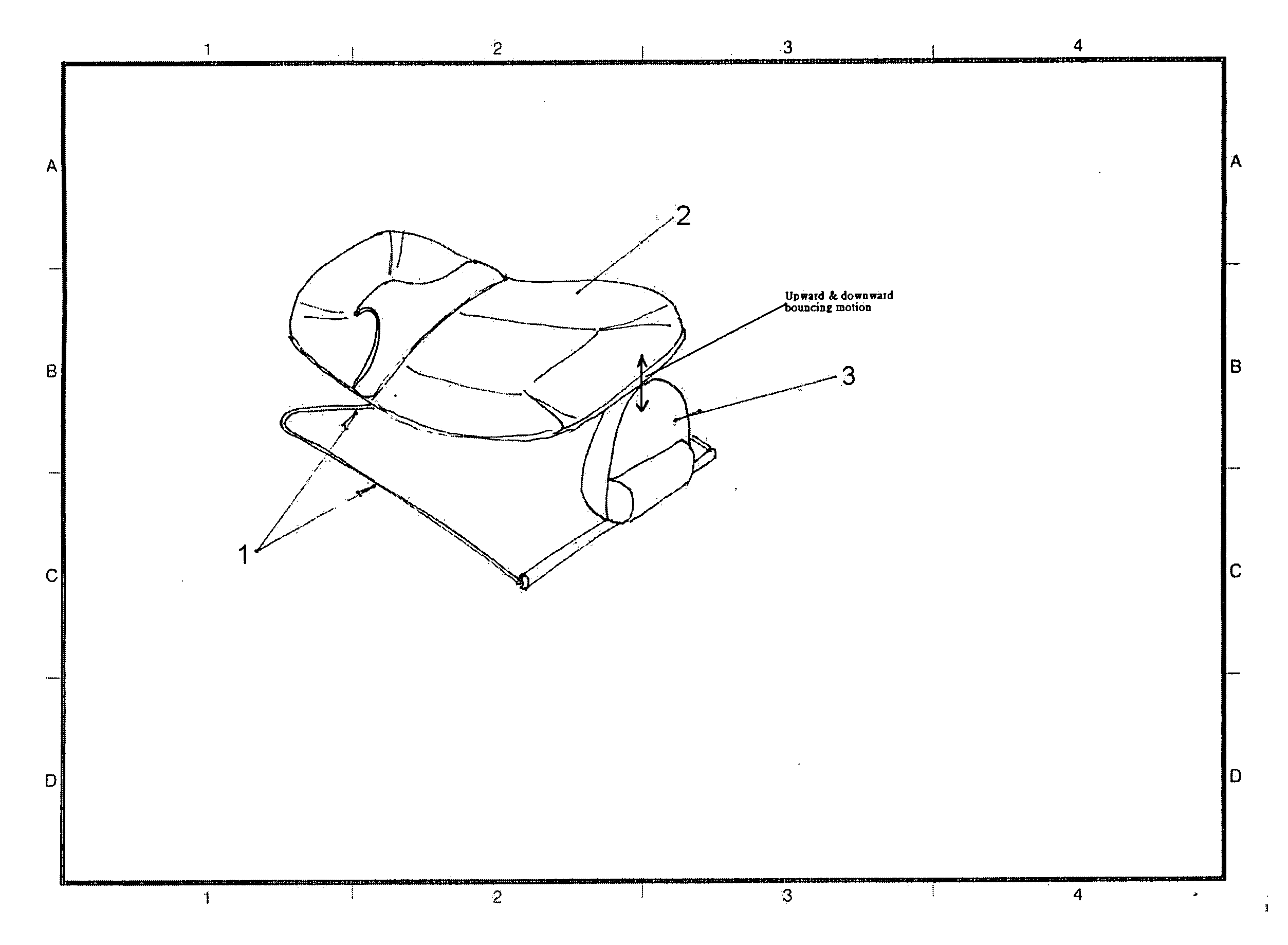
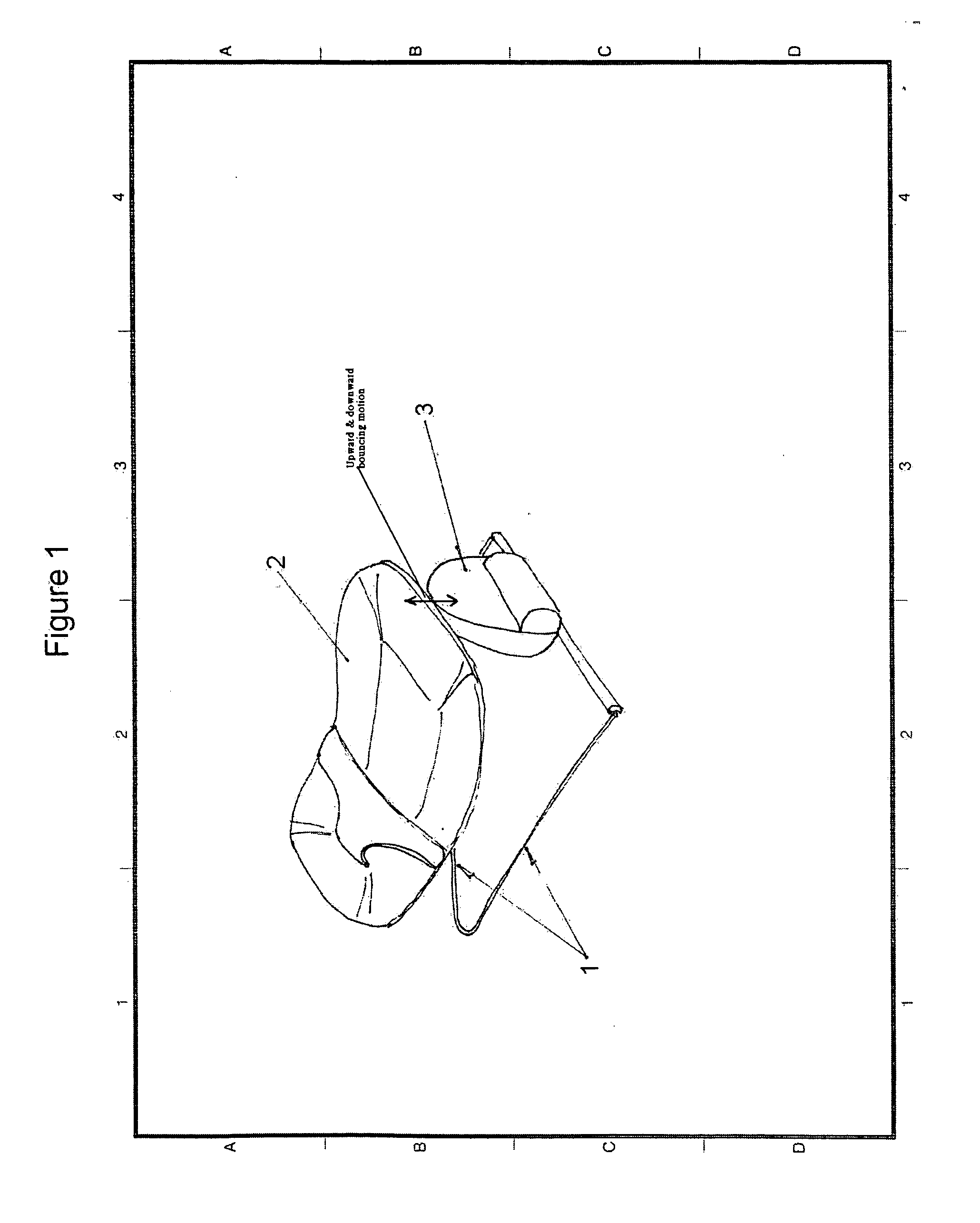
[0023]FIG. 1 depicts one purely illustrative embodiment of a baby bouncer system of the instant invention.

[0024] Referring to FIG. 1, resilient support frame 1 is adapted for positioning on a relatively level surface. Cradle-like bed 2 is attached to and supported by resilient support frame 1 in an elevated position suitable for stable support of a baby. Microprocessor-controlled actuator 3 can be affixed to resilient support frame 1 through any number of known means including but not limited to snaps, clamps, straps, detents, locks, and pins and is engaged for the transmission of bouncing force to bounce bed 2. In one embodiment, microprocessor-controlled actuator 3 hangs from resilient support frame 1 and transmits bouncing forces to the frame. Preferably, actuator 3 is attached only to the bouncing portion of bed 2 and detects and matches the natural bouncing frequency of resilient support frame 1. Most preferably, actuator 3 generates a gentle pull and push force at a rhythm ma...


PUM


Abstract

The invention provides a novel microprocessor-controlled actuator which bounces a baby bouncer system at soothing frequencies that are optimized for the weight of a baby supported in the baby bouncer system bed. The invention also provides a novel baby bouncer system which includes the novel microprocessor-controlled actuator. In one embodiment, the microprocessor based control system which controls the bouncing motion of the actuator also emits soothing sounds.

Description

FIELD OF THE INVENTION [0001] The invention provides a novel microprocessor-controlled actuator which bounces a baby bouncer system at soothing frequencies that are optimized for the weight of a baby supported in the baby bouncer system bed. The invention also provides a novel baby bouncer system which includes the novel microprocessor-controlled actuator. [0002] In one embodiment, the microprocessor based control system which controls the bouncing motion of the actuator also emits soothing sounds. BACKGROUND OF THE INVENTION [0003] A baby bouncer system comprises a cradle-like seat that supports and rocks a baby in a seated or prone position and a resilient metal frame that includes a base adaptable for support by a relatively uniform surface and an angled segment which extends upwardly to support the seat. The angled segment may be bent downwardly toward the base portion of the frame to provide a gentle rocking movement. The general configuration and design of baby bouncer frames ...

Claims


Application Information

Patent Timeline
IPC IPC(8): A47D9/02A47D13/10
CPCA47D9/02A47D13/107A47D13/10A47D9/04A47D9/057
Inventor WONG, SUI-KAYCHEUNG, KWOK YAU WILLIAM
Owner JETTA
Learn More