Vending machine

a vending machine and a technology of a vending machine body, applied in the field of vending machines, can solve the problems of reducing the buying inclination of prospective buyers, difficult to enable the replenishment to adequately catch up with the sale of commodities, and poor visual impression of prospective buyers

Inactive Publication Date: 2005-12-29
SANDEN CORP
View PDF5 Cites 19 Cited by
  • Summary
  • Abstract
  • Description
  • Claims
  • Application Information

AI Technical Summary

Benefits of technology

[0011] In this vending machine, the first commodity storing devices can be automatically replenished, without relying on manual work, with commodities from the second commodity storing devices by means of the commodity transferring device for regular use in selling. Therefore, it is possible to have commodity replenishment follow commodity sale, thereby to prevent the decreased number of commodities stored in the first commodity storing devices from deteriorating the impression that the prospective buyer would receive.

Problems solved by technology

In this vending machine, which permits visually recognition of stored commodities through the transparent panel from outside, when the storage number of commodities decreases with the progress of sale, the visual impression which the prospective buyer gets becomes poorer than when enough commodities are stored in the vending machine and the buying inclination of the prospective buyer declines.
Although the replenishment of commodities to the vending machine is performed by manual work of the operator or the like, it is difficult to enable the replenishment to adequately catch up with the sale of commodities.
If the replenishment fails to catch up, the stored commodities will unusually decrease and become sold out.

Method used


Image

  • Vending machine
  • Vending machine
  • Vending machine

Examples


Embodiment Construction

[0036]FIG. 1 to FIG. 18 show a preferred embodiment of the present invention.

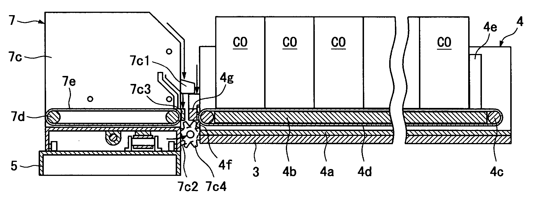
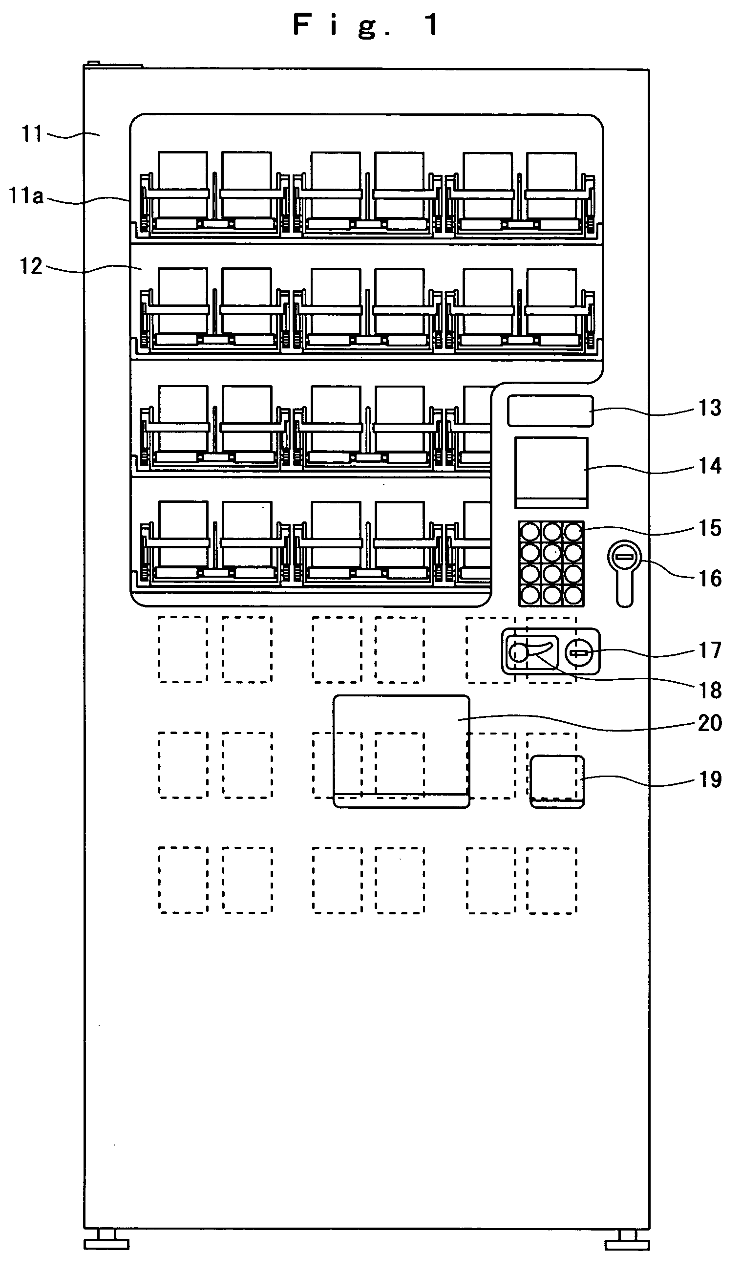
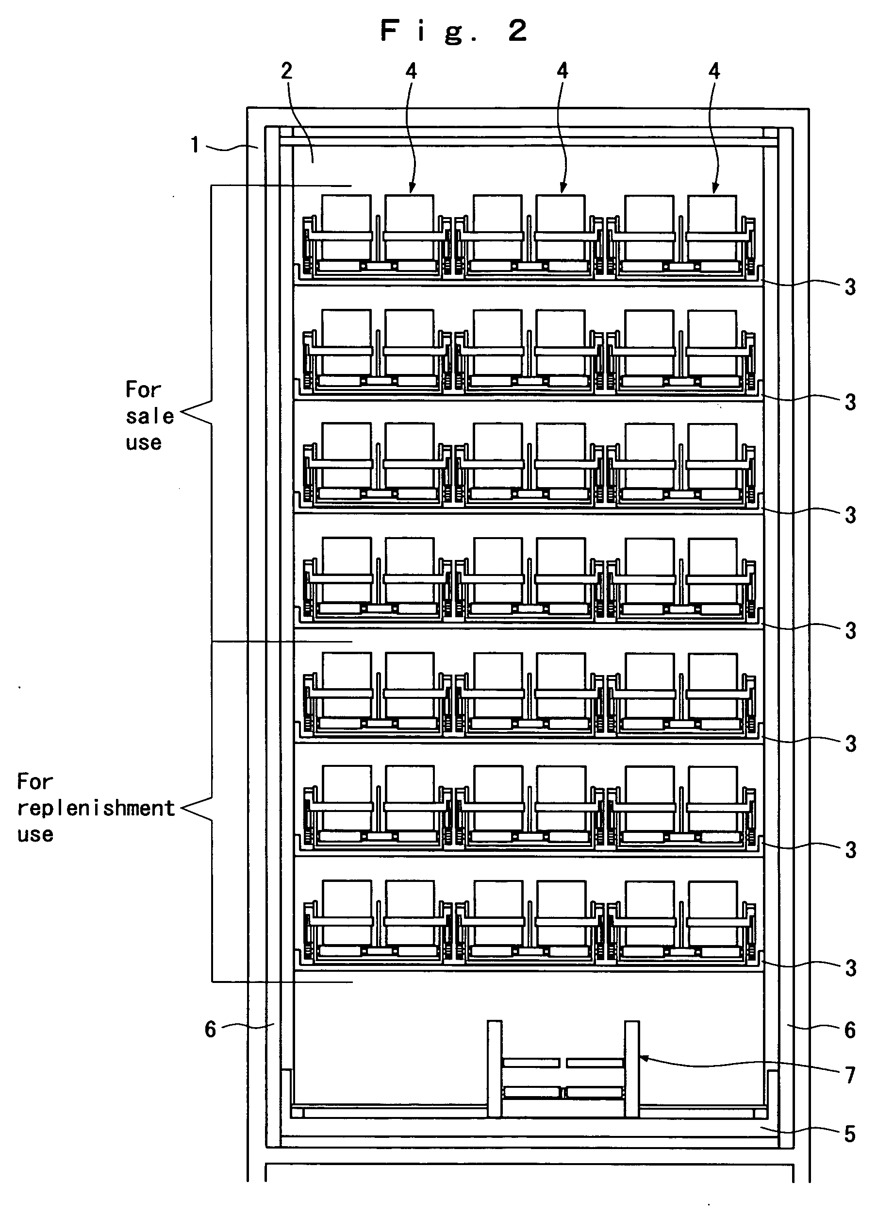
[0037]FIG. 1 shows a front view of a vending machine; FIG. 2 shows a front view of a cabinet, revealing the internal mechanism of the vending machine shown in FIG. 1; FIG. 3(A) shows a front view of a commodity storing device shown in FIG. 1 and FIG. 2; FIG. 3(B) shows a section along line a1-a1 in FIG. 3(A); FIG. 4 (A) shows a front view of a commodity bucket shown in FIG. 1 and FIG. 2; FIG. 4(B) shows a section along line a2-a2 in FIG. 4(A); FIG. 4(C) illustrates an operation of the commodity bucket; FIG. 5 shows a configuration of a control system; FIG. 6 is a flow chart of a commodity sale control; FIG. 7 to FIG. 12 illustrate commodity selling actions; FIG. 13 is a flow chart of a commodity replenishment control; FIG. 14 to FIG. 18 illustrate commodity replenishing actions.

[0038] To begin with, the mechanical configuration of the vending machine will be described with reference to FIG. 1 to FIG. 4(C)...


PUM


Abstract

A vending machine has commodity storing devices for sale use, commodity storing devices for replenishment use and a commodity transferring device. This vending machine performs usual sale operation by delivering a commodity in one of the commodity storing devices for sale use by means of the commodity transferring device to a commodity outlet, and replenishes one of the commodity storing devices with at least one commodity from one of the commodity storing devices for replenishment use by means of the commodity transferring device.

Description

BACKGROUND OF THE INVENTION [0001] 1. Field of the Invention [0002] The present invention relates to a vending machine for storing and selling commodities, and more particularly to a vending machine which makes stored commodities and selling actions visible from outside through a transparent panel. [0003] 2. Description of the Related Art [0004] A conventional vending machine of this kind usually has a transparent panel disposed on the front side of the vending machine, a plurality of commodity storing devices arranged in a prescribed form in the vending machine, and a commodity transferring device for receiving a commodity from one of the commodity storing devices and delivering the commodity to a commodity outlet. [0005] The commodity storing devices each have a belt which permit loading of commodities in tandem and can move in the back-and-forth direction. The commodity transferring device has a drive mechanism capable of moving the belt of one of the commodity storing devices in...

Claims


Application Information

Patent Timeline
Patent Type & Authority Applications(United States)
IPC IPC(8): B65H1/08G07F11/16G07F11/58
CPCG07F11/58
Inventor KENMOCHI, MITSUYUKI
Owner SANDEN CORP
Why Eureka
Try Eureka