Focus control apparatus and optical apparatus

a control apparatus and optical technology, applied in the direction of camera focusing arrangement, printers, instruments, etc., can solve the problems of low detection accuracy of control systems, parallax between subjects, and inability to maintain sufficient focal-point detecting accuracy for a distance-changing subject, etc., to achieve smooth and quick switching of af systems

Inactive Publication Date: 2005-12-29
CANON KK
View PDF8 Cites 44 Cited by
  • Summary
  • Abstract
  • Description
  • Claims
  • Application Information

AI Technical Summary

Benefits of technology

[0015] Another exemplary object of the present invention is to provide a focus control apparatus that smoothly and quickly switches the AF systems in the hybrid AF system.

Problems solved by technology

Problematically, these focus control systems have focal point detection accuracy lower than the contrast AF system because they use a dedicated detecting system subject to time and temperature variations, and cause a parallax between a subject and a distance-measuring position depending upon the distance.
However, the hybrid AF proposed in Japanese Patent Application, Publication No. 2001-255456 completely switches the AF system and has a problem in that it cannot maintain the sufficient focal-point detecting accuracy for a distance-changing subject.
In other words, while the contrast AF system can maintain the sufficient accuracy for a stationary subject, the triangulation AF system exclusively used for a dynamic or distance-changing subject is greatly subject to an erroneous measurement of a focal position due to the time and temperature variations, and causes a high pixel density image-pickup device an out-of-focus state, for example.
However, the hybrid AF system disclosed in Japanese Patent Application, Publication No. 2001-141984 causes two AF systems to detect focal points for different subjects, for example, due to the parallax.
When the contrast AF system cannot sufficiently detect a focal point after the triangulation AF system detects the focal point, the mode is again switched to the triangulation AF system and the focal position is possibly unavailable due to the temporary hunting.
A switching position is sometimes far from a focal position and sometimes close to it in the AF system, resulting in an unstable focus control.

Method used


Image

  • Focus control apparatus and optical apparatus
  • Focus control apparatus and optical apparatus
  • Focus control apparatus and optical apparatus

Examples


first embodiment

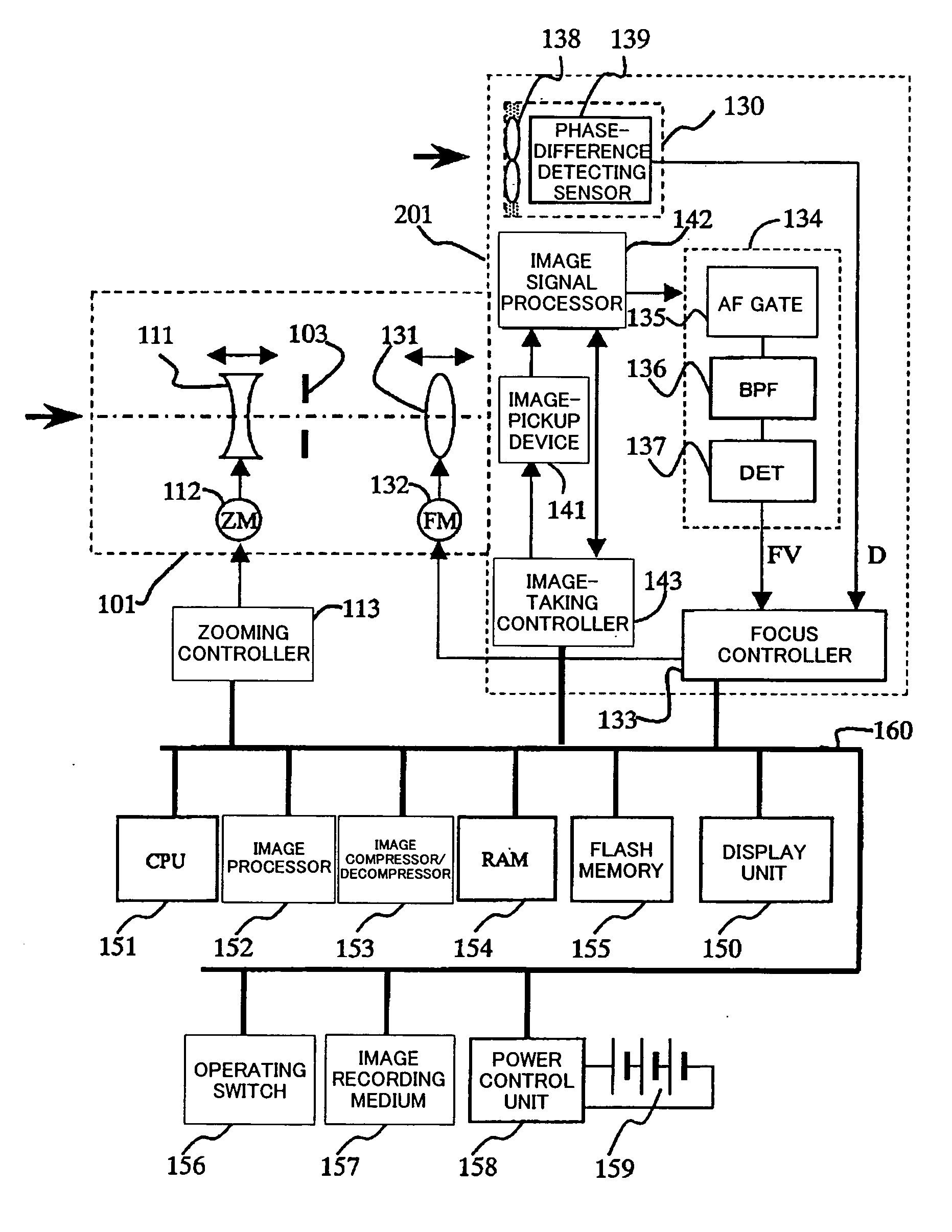
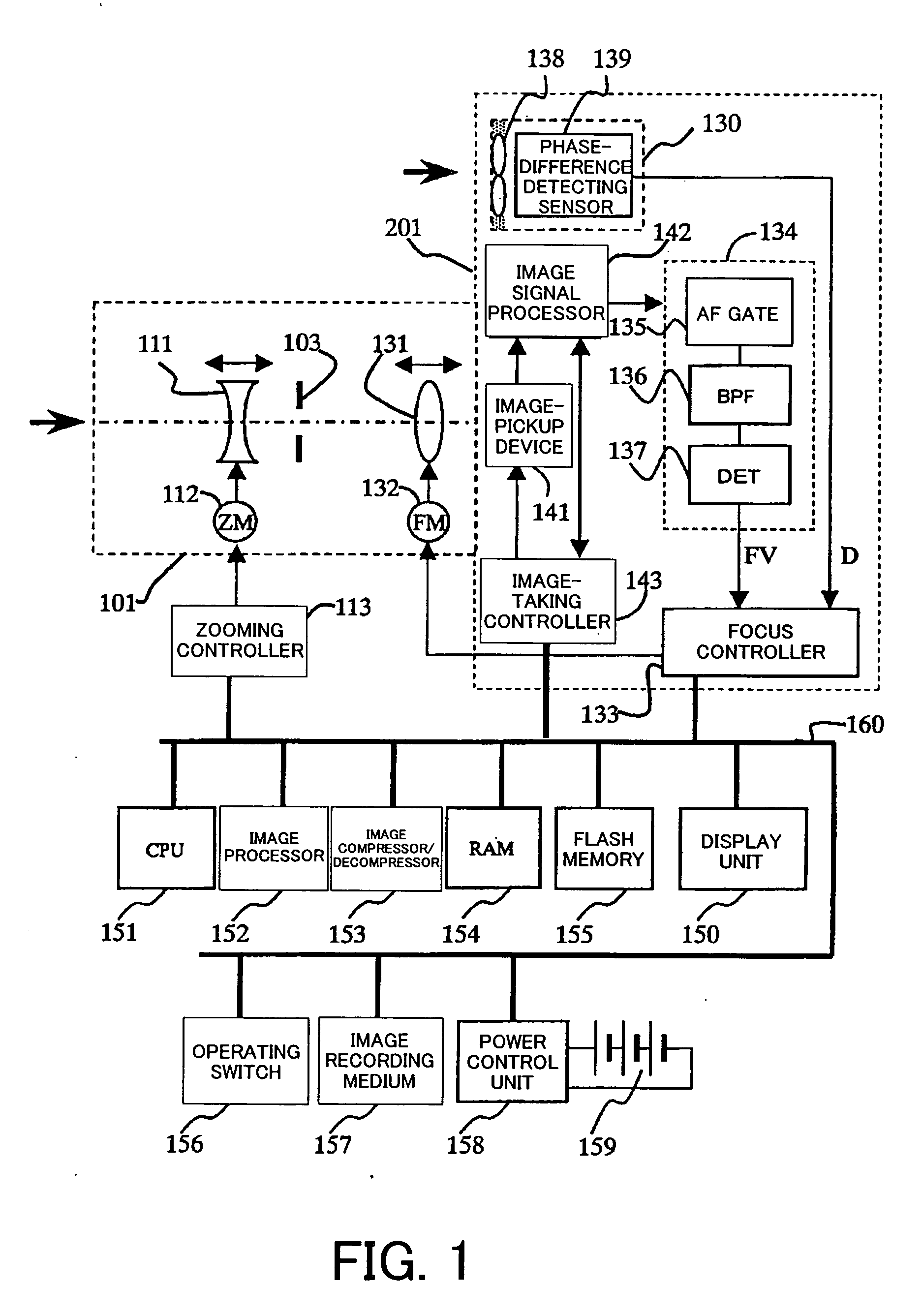
[0038]FIG. 1 is a schematic block diagram of a camera system according to a first embodiment of the present invention, including a camera body 201 and a lens unit 101 mounted on the camera body 201. While this embodiment shows a lens interchangeable camera system in which the lens unit 101 is attached to and detached from the camera body 201, the present invention is also applicable to a lens fixed camera system. While this embodiment discusses a digital still camera, the present invention is also applicable a video camera system. Each of the camera system, camera body and interchangeable lens are included in the inventive optical apparatus.

[0039] The lens unit 101 includes a zoom lens 111 that moves in an optical-axis direction and varies a focal length of a projection optical system, a focus lens 131 that moves in the optical-axis direction for focusing, and a light intensity adjusting member (or stop) 103 that adjusts the incident light intensity upon the image surface in accord...

second embodiment

[0076] FIGS. 5 to 8 show focus control in a camera system according to a second embodiment of the present invention. This embodiment provides contrast-detecting AF. The structure of the camera system in this embodiment is similar to that of the first embodiment, and similar components are designated by similar reference numerals.

[0077]FIG. 7 shows a transition in the normal contrast-detecting AF, where an ordinate axis denotes a level of the AF evaluation value FV, and an abscissa axis denotes a position of the focus lens 131. The right direction of the lens position denotes the infinity side, and the left direction denotes the close-up side. P701 to P705 show a relationship that varies with time between the focus lens position and the AF evaluation value FV.

[0078] At first, the focus lens 131 is located at a lens position P701 at time T701, and driven by a predetermined fine amount in a direction for increasing the AF evaluation value FV so as to search for a peak position of the...

third embodiment

[0108]FIG. 10 is a structural block diagram of a lens interchangeable camera system equipped with a focus control apparatus according to a third embodiment of the present invention.

[0109] The image-taking apparatus of this embodiment includes a camera body 301 and a lens unit 501 mounted on the camera body 301. While this embodiment shows a lens interchangeable camera system in which the lens unit 501 is attached to and detached from the camera body 301, the present invention is also applicable to a lens fixed camera system. While this embodiment discusses a digital still camera system, the present invention is also applicable a video camera system. Each of the camera system, camera body and interchangeable lens are included in the inventive optical apparatus.

[0110] The lens unit 501 includes a zoom lens 311 that moves in an optical-axis direction and varies a focal length of a projection optical system, a focus lens 231 that moves in the optical-axis direction for focusing, and a...


PUM


Abstract

A focus control apparatus includes a signal generator for generating a first signal in accordance with a predetermined frequency component of an image signal obtained by photoelectrically converting an image of a subject formed by an image-taking optical system, a detector for detecting a second signal different from the first signal, and a controller for detecting a movement of the subject based on the second signal and for switching driving of the image-taking optical system based on the detection, wherein the controller controls driving of the image-taking optical system based on the first signal.

Description

BACKGROUND OF THE INVENTION [0001] The present invention relates a focus control apparatus to be mounted in an optical apparatus, such as a camera. [0002] A contrast autofocus (“AF”) system among the AF control for use with a camera, etc. uses an image-pickup device for an image-taking optical system, and detects a high frequency component in a brightness signal obtained from the image-pickup device or a component of the contrast state (visibility) (referred to as an “AF evaluation value” hereinafter). The contrast AF system thereby provides highly precise, small and inexpensive AF control since no focal-point detecting system is required. [0003] Known as the contrast AF system are a full scan system that scans from infinity to a close-up end, detects an AF evaluation value, and moves a lens to a (focal) position corresponding to the maximum AF evaluation value, and a contrast detection system that moves a lens by a predetermined amount in a direction for increasing the AF evaluatio...

Claims


Application Information

Patent Timeline
Patent Type & Authority Applications(United States)
IPC IPC(8): H04N5/232
CPCH04N5/23212H04N23/672H04N23/673
Inventor SUDA, HIROFUMI
Owner CANON KK
Why Eureka
Try Eureka