Wireless communication system and semiconductor integrated circuit

a communication system and integrated circuit technology, applied in power management, instruments, electric/magnetic computing, etc., can solve the problems of increasing current consumption as the entire detection circuit, difficult design of temperature characteristics given to constant current sources, and high load design, and achieve excellent linearity of detection output

Inactive Publication Date: 2005-12-29
RENESAS ELECTRONICS CORP
View PDF4 Cites 49 Cited by
  • Summary
  • Abstract
  • Description
  • Claims
  • Application Information

AI Technical Summary

Benefits of technology

[0020] According to the present invention, a transmission power detection circuit can be achieved that has excellent linearity of detection output for transmission output power and can obtain detection output not having temperature dependence, and a wireless communication system using it can be realized.
[0021] Furthermore, according to the present invention, there can be realized a wireless communication system that can correctly perform limiter control that prevents transmission output from exceeding maximum transmission power, and a transmission power detection circuit suitable for wireless communication systems that perform limiter control.

Problems solved by technology

Therefore, with the detection circuit as shown in FIG. 13, the design of temperature characteristic given to the constant current source is difficult.
On the other hand, changing the temperature characteristic of the constant current source for each of the stages of the amplifiers would heavily load the design and require a different constant current source for each of stages of the amplifiers.
As a result, current consumption as the entire detection circuit would increase.

Method used


Image

  • Wireless communication system and semiconductor integrated circuit
  • Wireless communication system and semiconductor integrated circuit
  • Wireless communication system and semiconductor integrated circuit

Examples


Embodiment Construction

[0035] A preferred embodiment of the present invention will be described with reference to the accompanying drawings.

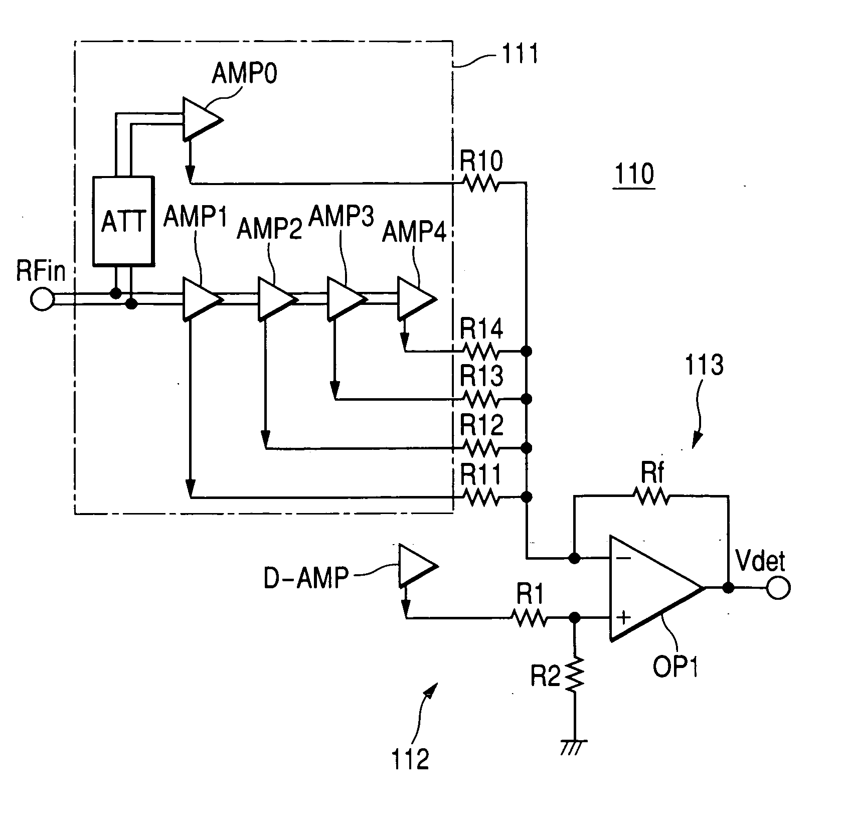
[0036]FIG. 1 shows an embodiment of a transmission power detection circuit according to the present invention.

[0037] The transmission power detection circuit 110 of this embodiment comprises: a rectifying detection part 111 that rectifies and detects an inputted radio frequency signal RFin; a compensation voltage generating circuit 112 that generates voltage for compensating temperature characteristics; and an addition / subtraction circuit 113. The rectifying detection part 111 comprises plural differential amplifiers AMP0 to AMP4 that input a radio frequency signal RFin captured by a coupler or the like from an output side of a radio frequency power amplifier (so-called power amplifier) not shown. The compensation voltage generating circuit 112 comprises a dummy amplifier D-AMP having a construction similar to the differential amplifiers, and a coefficient circuit c...


PUM


Abstract

A wireless communication system uses a transmission power detection circuit. The transmission power detection circuit has excellent linearity of detection output for transmission output power and can obtain detection output not having temperature dependence. The transmission power detection circuit has rectifying detection part that includes plural amplifiers connected in series and obtains detection output by taking out rectified outputs from emitters of input transistors of amplifiers of individual stages and synthesizes them. A compensation voltage generating circuit has a dummy amplifier having a construction similar to the amplifiers constituting the rectifying detection part and a coefficient circuit that changes output of the dummy amplifier at a specified ratio, and generates voltage for compensating temperature characteristics. Also included is an addition/subtraction circuit that obtains detection output free of temperature dependence by subtracting compensation voltage generated in the compensation voltage generating circuit from output voltage of the rectifying detection part.

Description

CROSS-REFERENCE TO RELATED APPLICATION [0001] The present application claims priority from Japanese paten application No. 2004-186039 filed on June 24, 2004, the content of which is hereby incorporated by reference into this application. BACKGROUND OF THE INVENTION [0002] The present invention relates to technology suitably applied to a detection circuit that is used in wireless communication systems such as cellular phones and detects power of transmission output, and more particularly to technology suitably applied to an output power detection circuit in a wireless communication system that controls output power so as not to exceed specified maximum transmission power. [0003] Generally, a transmission output part in wireless communication devices (mobile communication devices) such as cellular phones is provided with a radio frequency power amplifier circuit that amplifies a modulated transmission signal. In the wireless communication devices, control is performed so that desired ...

Claims


Application Information

Patent Timeline
Patent Type & Authority Applications(United States)
IPC IPC(8): H01Q11/12H03F3/21H04B7/00H04B7/005
CPCH04W52/52
Inventor YOSHIMI, DAISUKEYAMAMOTO, AKIOIGARASHI, YUTAKA
Owner RENESAS ELECTRONICS CORP
Why Eureka
Try Eureka