Front derailleur for bicycle

Inactive Publication Date: 2005-12-29
SHIMANO INC
View PDF17 Cites 5 Cited by
  • Summary
  • Abstract
  • Description
  • Claims
  • Application Information

AI Technical Summary

Benefits of technology

[0009] One object of the present invention is to provide a front derailleur of a bicycle in w

Problems solved by technology

As a result, the shifting operation becomes difficult because a greater force is required for the gear shift operation when the gear shift operation is performed manually by a gear shifting member.
Also, when the

Method used


Image

  • Front derailleur for bicycle
  • Front derailleur for bicycle
  • Front derailleur for bicycle

Examples


Example

[0041] In the first embodiment of the present invention, the inner link 42 is preferably disposed below the base bracket 40 when the base bracket 40 is installed on the seat tube 102a as seen in FIG. 7. Both upper and lower ends of the inner link 42 are freely rotatably connected to the base bracket 40 and the chain guide 41, respectively. The inner link 42 has the upper end (first section) that is freely swingably connected between the inner link support portions 50b of the first base member 50. The lower end (second section) of the inner link 42 is freely swingably connected to the chain guide 41.

[0042] The outer link 43 is disposed farther apart from the base bracket 40 with respect to the inner link 42. The inner link 42 and the outer link 43 are arranged substantially parallel to each other. Both ends of the outer link 43 are freely swingably connected to the outer link support portions 50c of the base bracket 40 and the chain guide 41. In other words, the outer link 43 includ...

Example

Second Embodiment

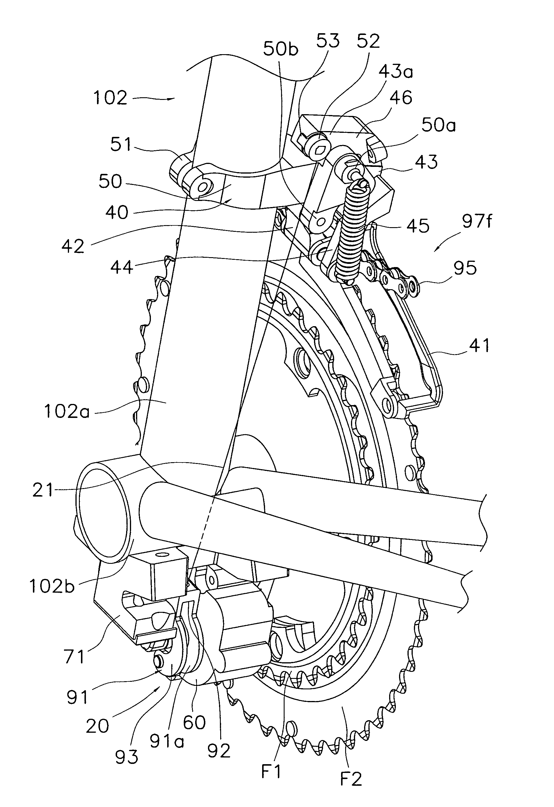
[0061] Referring now to FIGS. 13 and 14, a front derailleur 197f in accordance with a second embodiment will now be explained. In view of the similarity between the first and second embodiments, the parts of the second embodiment that are identical to the parts of the first embodiment will be given the same reference numerals as the parts of the first embodiment. Moreover, the descriptions of the parts of the second embodiment that are identical to the parts of the first embodiment may be omitted for the sake of brevity.

[0062] The difference between the front derailleur 97f of the first embodiment and the front derailleur 197f of the second embodiment is that, although the front derailleur 97f of the first embodiment is arranged as a down-swing type down-pull derailleur wherein the inner link 42 and the outer link 43 swing under the base bracket 40, the front derailleur 197f of the second embodiment is arranged as a top-swing type derailleur wherein an inner link ...

Example

Third Embodiment

[0067] Referring now to FIGS. 15 and 16, a front derailleur 297f in accordance with a third embodiment will now be explained. In view of the similarity between the first and third embodiments, the parts of the third embodiment that are identical to the parts of the first embodiment will be given the same reference numerals as the parts of the first embodiment. Moreover, the descriptions of the parts of the third embodiment that are identical to the parts of the first embodiment may be omitted for the sake of brevity.

[0068] As seen in FIGS. 15 and 16, the front derailleur 297f of the third embodiment is arranged as a down-pull top swing type derailleur. When the front derailleur 297f is arranged as the down-pull top swing type derailleur, in order to avoid an interference of a cable retaining portion 242a disposed in an opposite side of the cable retaining portion 142a as shown in FIGS. 13 and 14, a first arm portion 244 extends upwardly from a center portion of the...


PUM


Abstract

A front derailleur basically comprises a base member, a chain guide, inner and outer links, a first arm portion, and a coil spring. The chain guide is freely swingably coupled to the base member to guide a chain in a direction of shifting gears. Each of the outer link and the inner link has first and second sections freely rotatably coupled to the base member and the chain guide, respectively. The outer link and the inner link are disposed substantially parallel to each other. The first arm portion extends in a direction away from the base member. The coil spring has first and second ends connected to the base member and a free end of the first arm portion such that a biasing force is applied on the chain guide in a direction toward a frame of the bicycle when the base member is installed on the frame.

Description

CROSS-REFERENCE TO RELATED APPLICATIONS [0001] This application claims priority to Japanese Patent Application No. 2004-184430. The entire disclosure of Japanese Patent Application No. 2004-184430 is hereby incorporated herein by reference. BACKGROUND OF THE INVENTION [0002] 1. Field of the Invention [0003] The invention relates to a bicycle derailleur. More specifically, this invention relates to a front derailleur for a bicycle adapted to be installed on a frame of the bicycle, configured and arranged to be connected to a gear shift to guide a chain into one of a plurality of gear shifting positions in accordance with movement of the gear shifting cable. [0004] 2. Background Information [0005] Japanese Laid-Open Patent Publication No. H08-169382 discloses a conventional a gear shifting device of a bicycle, a front derailleur, which is configured and arranged to guide a chain into one of a plurality of front sprockets. The conventional front derailleur is provided with a base membe...

Claims


Application Information

Patent Timeline
IPC IPC(8): B62M9/131B62M9/132B62M9/1342
CPCB62M9/1348B62M9/132
Inventor ICHIDA, TADASHIFUJII, KAZUHIRO
Owner SHIMANO INC
Why Eureka
Try Eureka