Nebulizing apparatus for medical use with improved nozzle positioning structure

a technology of nozzle positioning and nozzle, which is applied in the direction of medical atomisers, inhalators, etc., can solve the problems of user inconvenience and other problems, and achieve the effects of maintaining the sanitary condition of the nozzle, saving space, and keeping the nozzle clean

Inactive Publication Date: 2006-01-05
K JUMP HEALTH
View PDF23 Cites 61 Cited by
  • Summary
  • Abstract
  • Description
  • Claims
  • Application Information

AI Technical Summary

Benefits of technology

[0005] The objective of the present invention is to provide a nebulizing apparatus for medical use with improved nozzle positioning structure capable of adjusting and fixing the direction of the nozzle according to a user.
[0006] In order to achieve the foregoing objective, the present invention provides a nebulizing apparatus for medical use with improved nozzle positioning structure including a nozzle and a nebulizing device connected to each other by means engagement protrusions and engagement grooves. A cover of the nebulizing device is provided with a plurality of engagement grooves and lumpy portions disposed around the inner wall and outer wall of the cover. An input portion of the nozzle has an engagement protrusion which can be assembled corresponding to the inner wall engagement grooves of the cover to fix the position the nozzle. The nozzle can then be pulled out, rotates to suitable angle and then installed to the cover of the nebulizing device if a different direction of the nozzle is desired.
[0007] It is another objective of the present invention that the nozzle can be stored inside the protective cover to maintain the sanitary condition of the nozzle after usage of the nebulizing apparatus.
[0008] In order to achieve the foregoing objectives, the present invention discloses a protective cover having two fixing portions which are disposed on an inner wall of the protective cover and in accordance with the input portion of the nozzle, such that the input portion of the nozzle is embedded between the two fixing portions during installation and cannot be dropped. Then, the protective cover is disposed on the main body for further receiving the nozzle so as to save space and keep the nozzle clean.

Problems solved by technology

Nevertheless, since the output device can rotate smoothly on the nebulizing device, user often experiencing inconveniences when trying to fix the direction of the output device, which easily swiveling around the annular groove whenever it is touched incautiously.

Method used


Image

  • Nebulizing apparatus for medical use with improved nozzle positioning structure
  • Nebulizing apparatus for medical use with improved nozzle positioning structure
  • Nebulizing apparatus for medical use with improved nozzle positioning structure

Examples


Embodiment Construction

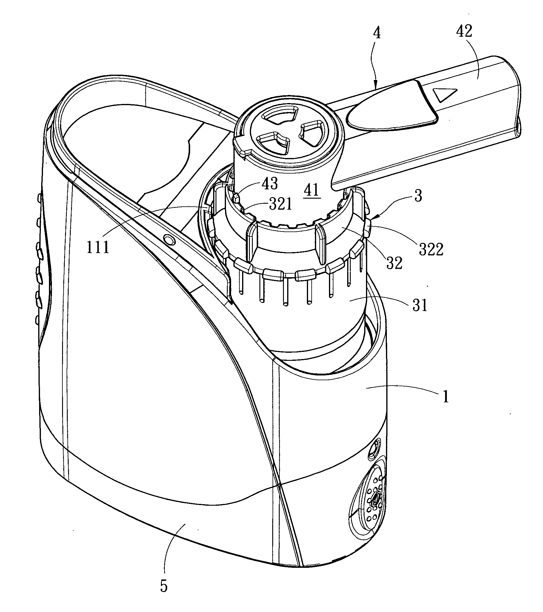
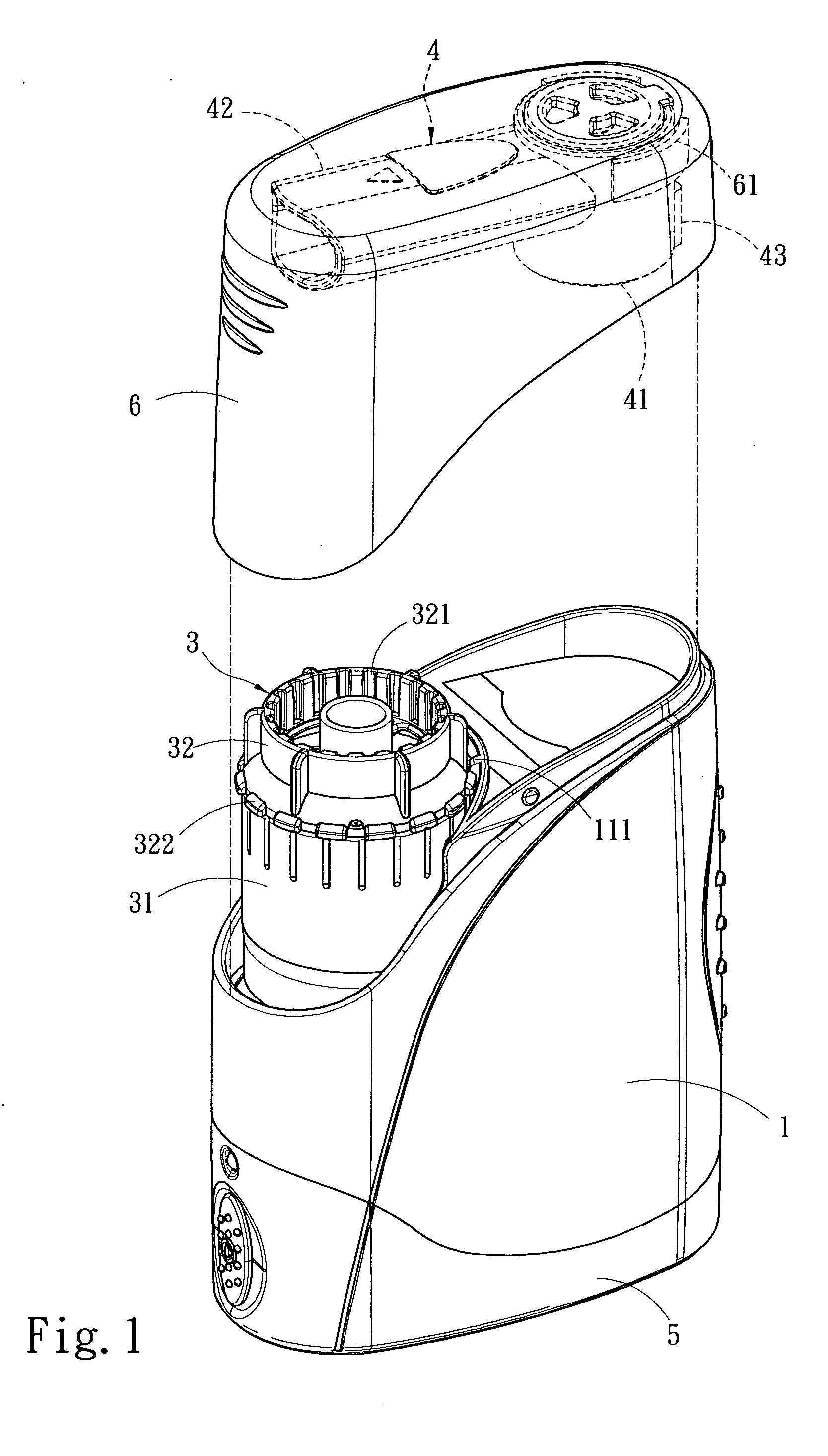
[0014] Referring to FIG. 1, it depicts a perspective schematic view of a nebulizing apparatus for medical use with improved nozzle positioning structure of the present invention. As shown in FIG. 1, the apparatus includes a main body 1 provided with an air compressor 2 disposed therein (shown in FIG. 2), a nebulizing device 3 to receive liquid medicine installed on the air compressor 2, a nozzle 4 installed on the nebulizing device 3, a bottom base 5 installed on a bottom of the main body 1, and a protective cover 6 installed on the main body 1 and receiving the nozzle 4. The air compressor 2 of the present invention compresses the air in high speed and transport the compressed air to the nebulizing device 3. The nebulizing device 3 nebulizes the liquid medicine, and the nozzle 4 outputs the nebulized liquid medicine for medical use.

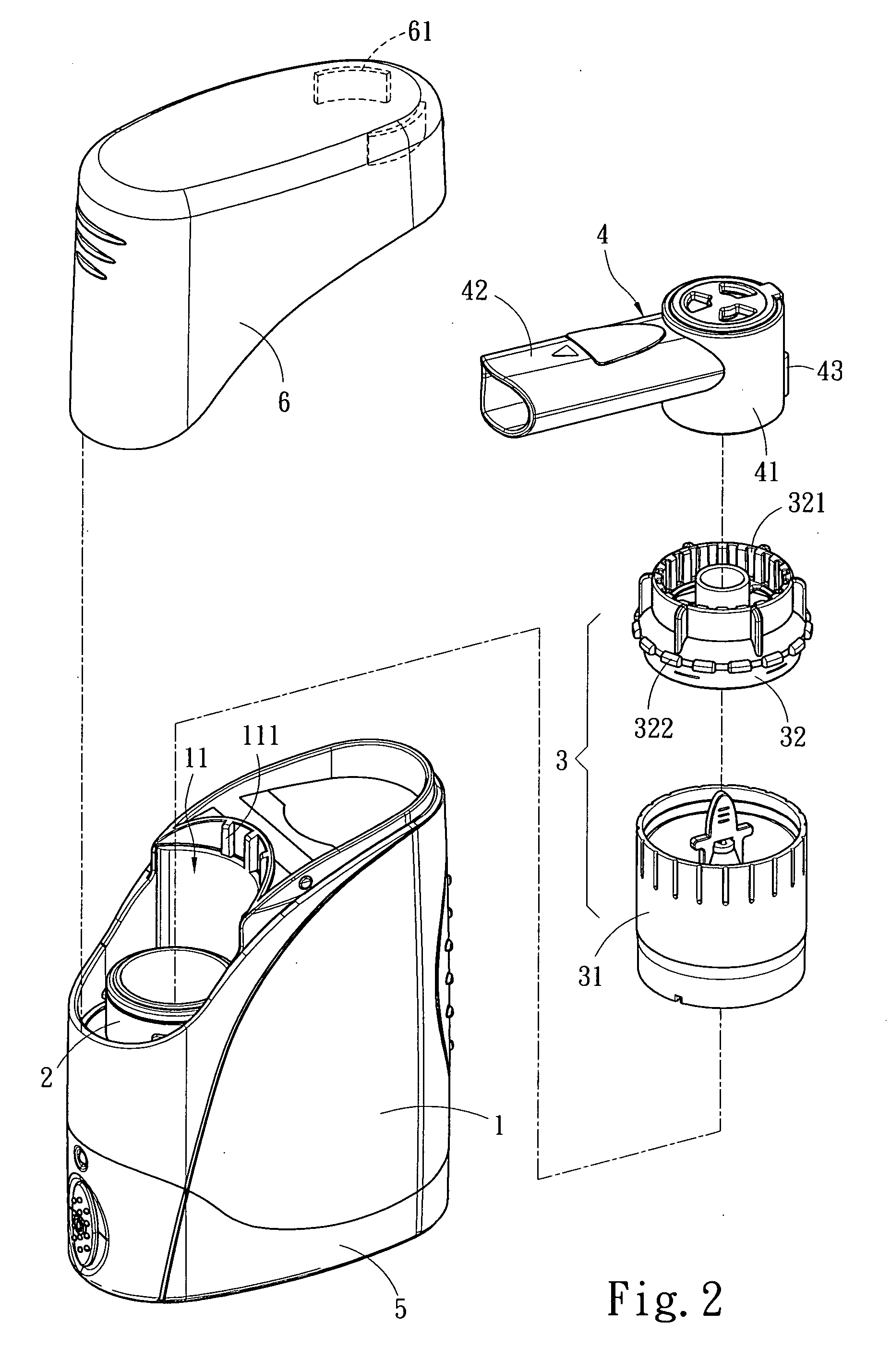
[0015] Referring to FIG. 2, it depicts a perspective exploded schematic view of a nebulizing apparatus for medical use with improved nozzle positioning...


PUM


Abstract

A nebulizing apparatus for medical use with a nozzle positioning structure, in which the direction of the nozzle can be adjusted and fixed according to the user. The nozzle and the nebulizing device are connected to each other by engagement protrusion and engagement grooves. The nozzle can be pulled out, rotated to a suitable angle and then installed on the cover of the nebulizing device if a different direction of the nozzle is desired.

Description

FIELD OF THE INVENTION [0001] A nebulizing apparatus for medical use with improved nozzle positioning structure, and more particularly to a nebulizing apparatus for medical use with improved nozzle positioning structure having a nozzle and a nebulizing device connected to each other by means of engagement protrusions and engagement grooves. BACKGROUND OF THE INVENTION [0002] In the prior arts, Taiwan Patent No. 567855 and U.S. Publication No. 2001 / 0002592 A1 disclosed an apparatus for nebulizing a liquid for medical use nebulizes a liquid medicine to fully generate the cure effect and includes a main body provided with an air compressor disposed therein, a nebulizing device to receive liquid medicine connected to the air compressor the liquid medicine, and an output device. The air compressor compresses the air in high speed and delivers the compressed air to the nebulizing device. The nebulizing device nebulizes the liquid medicine, and the output device outputs the nebulized liqui...

Claims


Application Information

Patent Timeline
Patent Type & Authority Applications(United States)
IPC IPC(8): A61M11/00
CPCA61M15/00
Inventor TSENG, DANIEL C.M.
Owner K JUMP HEALTH
Why Eureka
Try Eureka