Apparatus and method for constructing and packaging printed antenna devices

a technology of printed antennas and antenna devices, applied in the structure of radiating elements, resonance antennas, antenna earthings, etc., can solve the problems of reducing antenna efficiency, limiting the bandwidth-efficiency product that can be achieved, and reducing the efficiency of antennas, so as to enhance the directivity of the antenna, reduce radiation, and enhance the hemispherical radiation pattern of the antenna

Active Publication Date: 2006-01-05
IBM CORP
View PDF13 Cites 98 Cited by
  • Summary
  • Abstract
  • Description
  • Claims
  • Application Information

AI Technical Summary

Benefits of technology

[0010] In yet another exemplary embodiment of the invention, the antenna includes a beamshaping pattern formed on first surface of the planar substrate, a second surface opposite the first surface of the planar substrate, or both the first surface and second surface of the planar substrate, to reduce radiation in a direction along the plane of the planar substrate and / or to enhance a hemispherical radiation pattern of the antenna (i.e., enhance directivity of the antenna).
[0011] Exemplary embodiments of the invention further include apparatus and methods for integrally packaging printed antenna devices according to the invention with IC (integrated circuit) chips (e.g., transceiver) to construct IC packages for, e.g., wireless communications applications. In particular, printed antenna devices according to embodiments of the invention can efficiently operate with relatively small ground planes, which enables compact packaging of such antennas with IC chips (e.g., a transceiver IC chip, a receiver or transmitter chip, and / or other IC chips) in a relatively small package similar in size to that of existing leaded carriers or leadless chip carriers for, e.g., transceiver ICs.

Problems solved by technology

One significant disadvantage of a conventional printed antenna device having a framework as shown in FIG. 1 is that such design provides a limit on the bandwidth-efficiency product that can be achieved.
Indeed, a higher bandwidth can typically be achieved only at the cost of efficiency.
Antenna efficiency will decrease due to resistive losses and impedance mismatches.
However, the tolerances of the etching technology that is used for generating feed and antenna patterns on a PTFE-based substrates together with via capabilities are not meeting the requirements if the antenna is desired to be connected to a MMW (millimeter wave) IC via C4 balls.
Indeed, currently available metal deposition methods (thin film technology) that provide sufficient tolerances cannot be applied to PTFE-based materials.
Additionally the bandwidth-efficiency product resulting from the use of a PTFE-based substrate is not sufficient for all applications.

Method used


Image

  • Apparatus and method for constructing and packaging printed antenna devices
  • Apparatus and method for constructing and packaging printed antenna devices
  • Apparatus and method for constructing and packaging printed antenna devices

Examples


Embodiment Construction

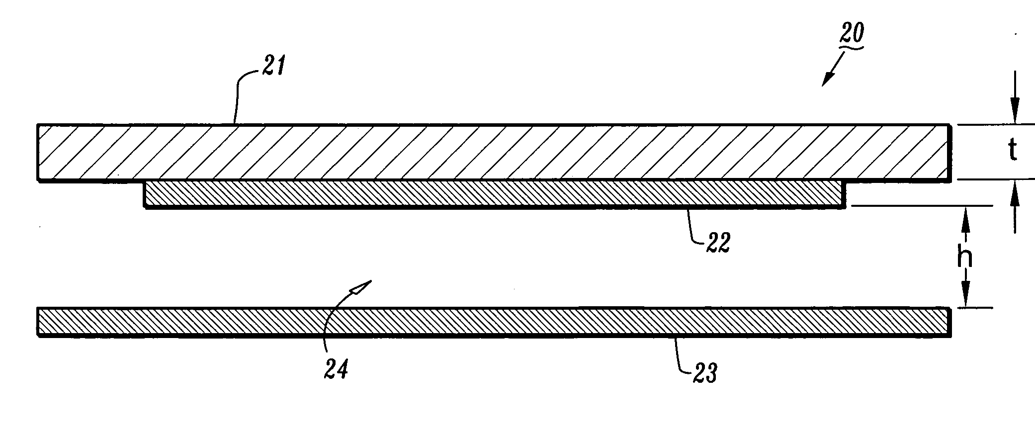
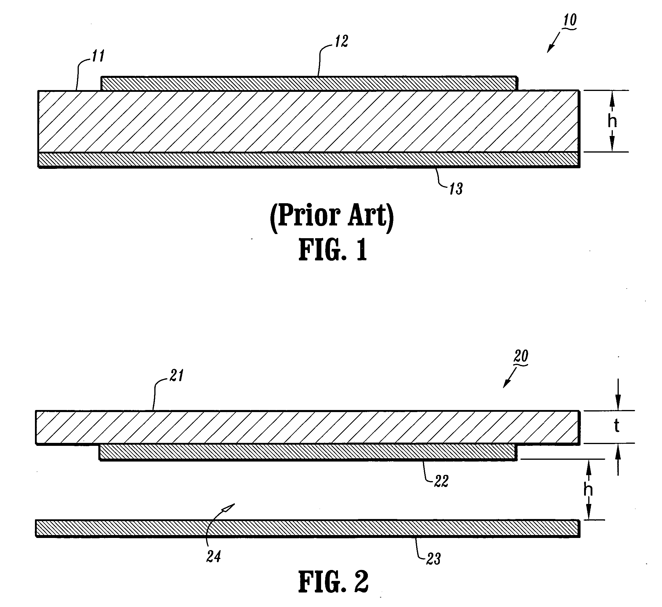
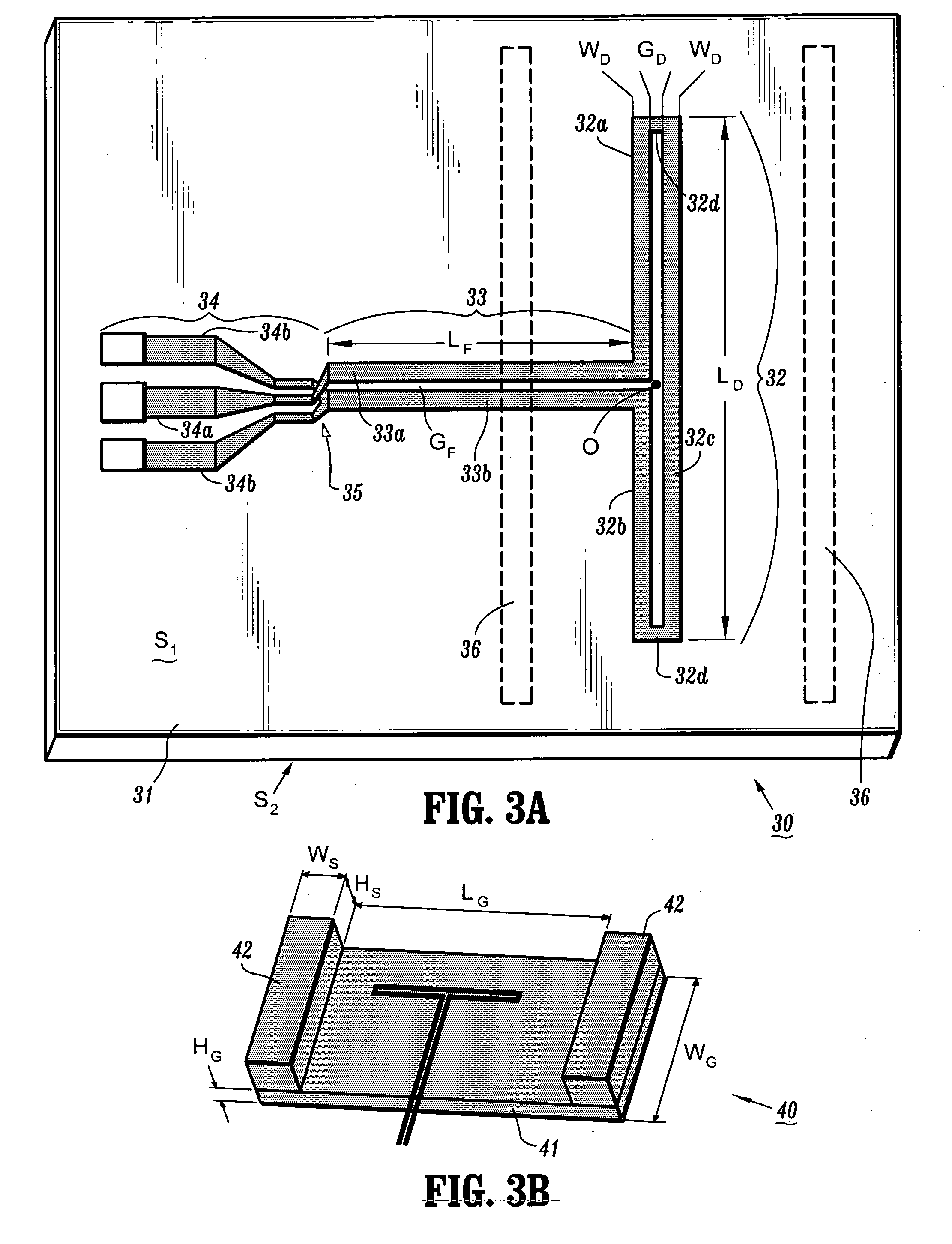
[0022] Exemplary embodiments of the invention generally include printed antenna devices that can operate at RF and microwave frequencies, for example, while simultaneously providing antenna performance characteristics such as high gain / directivity / radiation efficiency, high bandwidth, hemispherical radiation patterns, impedance, etc., that render the antennas suitable for voice communication, data communication or RADAR applications, for example. Exemplary embodiments of the invention further include apparatus and methods for integrally packaging printed antenna devices according to the invention with IC (integrated circuit) chips (e.g., transceiver) to construct IC packages for, e.g., wireless communications applications. In particular, printed antenna devices according to embodiments of the invention can efficiently operate with relatively small ground planes, which enables compact packaging of such antennas with IC chips (e.g., transceiver IC chip) in a relatively small package s...


PUM


Abstract

Printed antenna devices are provided, which can operate at RF and microwave frequencies, for example, while simultaneously providing antenna performance characteristics such as high gain/directivity/radiation efficiency, high bandwidth, hemispherical radiation patterns, impedance, etc., that render the antennas suitable for voice communication, data communication or radar applications, for example. Further, apparatus are provided for integrally packaging such printed antenna devices with IC (integrated circuit) chips (e.g., transceiver) to construct IC packages for, e.g., wireless communications applications.

Description

TECHNICAL FIELD OF THE INVENTION [0001] The present invention relates generally to antennas for wireless or RF (radio frequency) communications systems and, more specifically, printed antenna designs that provide both high bandwidth and efficiency with substantially hemispherical radiation patterns, as well as apparatus and methods for packaging such antennas with IC (integrated circuit) chips. BACKGROUND [0002] To provide wireless connectivity and communication between devices in a wireless network such as a wireless PAN (personal area network), a wireless LAN (local area network) a wireless WAN (wide area network), a cellular network, or virtually any radio network or system), it is necessary to equip the receivers and transmitters (or tranceivers) with antennas to efficiently radiate (transmit) or receiver the desired signals to / from other elements of the network. [0003] Various types of antennas may be implemented in such communications networks and devices including, for exampl...

Claims


Application Information

Patent Timeline
Patent Type & Authority Applications(United States)
IPC IPC(8): H01Q1/26
CPCH01Q9/26H01L2223/6677H01L2224/16225H01L2224/48227H01L2924/3011H01L2224/73207H01L2924/00H01L2224/04042G01R29/10
Inventor GAUCHER, BRIAN PAULLIU, DUIXIANPFEIFFER, ULLRICH RICHARD RUDOLFZWICK, THOMAS MARTIN
Owner IBM CORP
Why Eureka
Try Eureka