Dry erase article

a technology of dry erase and articles, applied in the field of dry erase articles, can solve the problems of difficult mounting of dry erase products, inconvenient transportation to meetings, and inconvenient transportation of dry erase materials,

Inactive Publication Date: 2006-01-05
3M INNOVATIVE PROPERTIES CO
View PDF58 Cites 33 Cited by
  • Summary
  • Abstract
  • Description
  • Claims
  • Application Information

AI Technical Summary

Problems solved by technology

In practice, inks intended for use with dry erase surfaces are often specifically formulated for use with individual surface compositions, and may not be useful on all types of dry erase materials.
The larger conventional dry erase products are disadvantaged in that they are heavy, and typically designed for permanent mounting on the wall, which makes them ill-suited for transportation to meetings and also for mounting on office partition walls.
Also, these dry erase products are often difficult to mount, typically requiring the use of power tools.
The smaller dry erase boards provide limited space for written material.
The cost of these transportable boards can be quite expensive.
Many of the mobile boards are only marginally easy to transport and require installation at the destination using either a wall-mounted rail or separate cubicle hooks.
Additionally, these boards are stiff and awkward to carry, and the desire for a compact carrying size limits the available writing area.
Moreover, transportability often means a loss of other desirable product features.
The thin sheet format of the surface allows the user to erroneously write past the edge of the sheet, which can cause the user to write on the underlying surface (e.g. a wall), resulting in unsightly marks.
The thin sheets similarly do not adequately prevent accidental movement of the eraser past the edge of the sheet, which can result in unsightly “smudging” of the wall due to deposition of ink dust by the eraser.
Additionally, means to mount the boards, as well as means to store markers and erasers are often absent from these products.
The mounting mechanisms used often result in sagging of the sheet, due to the flexible nature of the surface.

Method used


Image

  • Dry erase article
  • Dry erase article
  • Dry erase article

Examples


example 1

Fabrication of a Decorative, Snag Resistant, Self-Engaging Fastener Material

[0066] A mixture was formed comprising 76.6% by weight of a polypropylene copolymer (Marlex HGZ-180, available from Phillips Sumika Polypropylene Company, The Woodlands, Tex.), 19.2% by weight of an impact modifying polypropylene resin (Adflex KS359P, available from Montell Polyolefins, Wilmington, Del.), 0.2% by weight of a blue colorant (IRGALITE® Blue GLG available from Ciba Specialty Chemicals, Tarrytown, N.Y.), and 4.0% of a fmely divided reflective material (used as a decorative agent). The resin mixture was melted and conveyed with a single screw extruder (Davis Standard, Somerville, N.J.). The extruder had a diameter of 6.35 cm (2.5 in), a length:diameter ratio (L / D) of 24 / 1, and a rising temperature profile ranging from 199° C. (390° F.) in the first zone after introduction to 218° C. (425° F.) in the final downstream zone. The polymer was passed through the extruder and continuously discharged at ...

example 2

Disengagement of Various Fastener Materials from Knitted Clothing

[0068] Pieces of fabric were cut from a knitted sweater (50% acrylic, 50% wool, Laura Scott Petite, Item # 33372, available from J. C. Penney Corporation, Inc., Plano, Tex.). A piece of male fastener material was placed on the outward facing side of each piece of fabric with the engagement surface of the fastener material against the fabric, and the two pieces were pressed together firmly. They were then placed together under an optical microscope, and micrographs were taken as the male fastener materials were separated from the knitted fabric material using tweezers. FIG. 5A is a micrograph image showing 3M™ Scotchmate™ fastener, male, cut loop type (available from 3M Company, St. Paul, Minn.). Threads of fabric are engaged strongly by this fastener system, and are clearly seen being pulled from the fabric during disengagement. FIG. 5B is a micrograph image showing Velcro® Industrial Strength Reclosable Fastener, mal...

example 3

Disengagement Force Required to Remove Various Fastener Materials from Carpet and Knitted Clothing

[0069] The disengagement forces required to separate a number of male fastener materials from various fabrics were measured. The fabrics were samples cut from knitted clothing (sweaters), as well as household carpeting. The sample numbers and descriptions of the fastener materials and the fabric samples are listed in Table 1.

TABLE 1Sample Numbers and Descriptions ofMale Fastener and Fabric MaterialsSampleDescription3.1Velcro ® Industrial Strength Reclosable Fastener,molded hook type, available from Velcro USA Inc.,Manchester, NH3.23M ™ Scotchmate ™ Hook and Loop Fastener, maleportion, cut loop type, available from 3M Company,St. Paul, MN3.33M ™ Command ™ Removable Interlocking Fasteners,available from 3M Company, St. Paul, MN3.4Scotch ® Reclosable Fastener, available from 3MCompany, St. Paul, MN3.5Snag-resistant fastener of Example 13.AKnitted sweater; 50% acrylic, 50% wool; Laura Sc...


PUM


Abstract

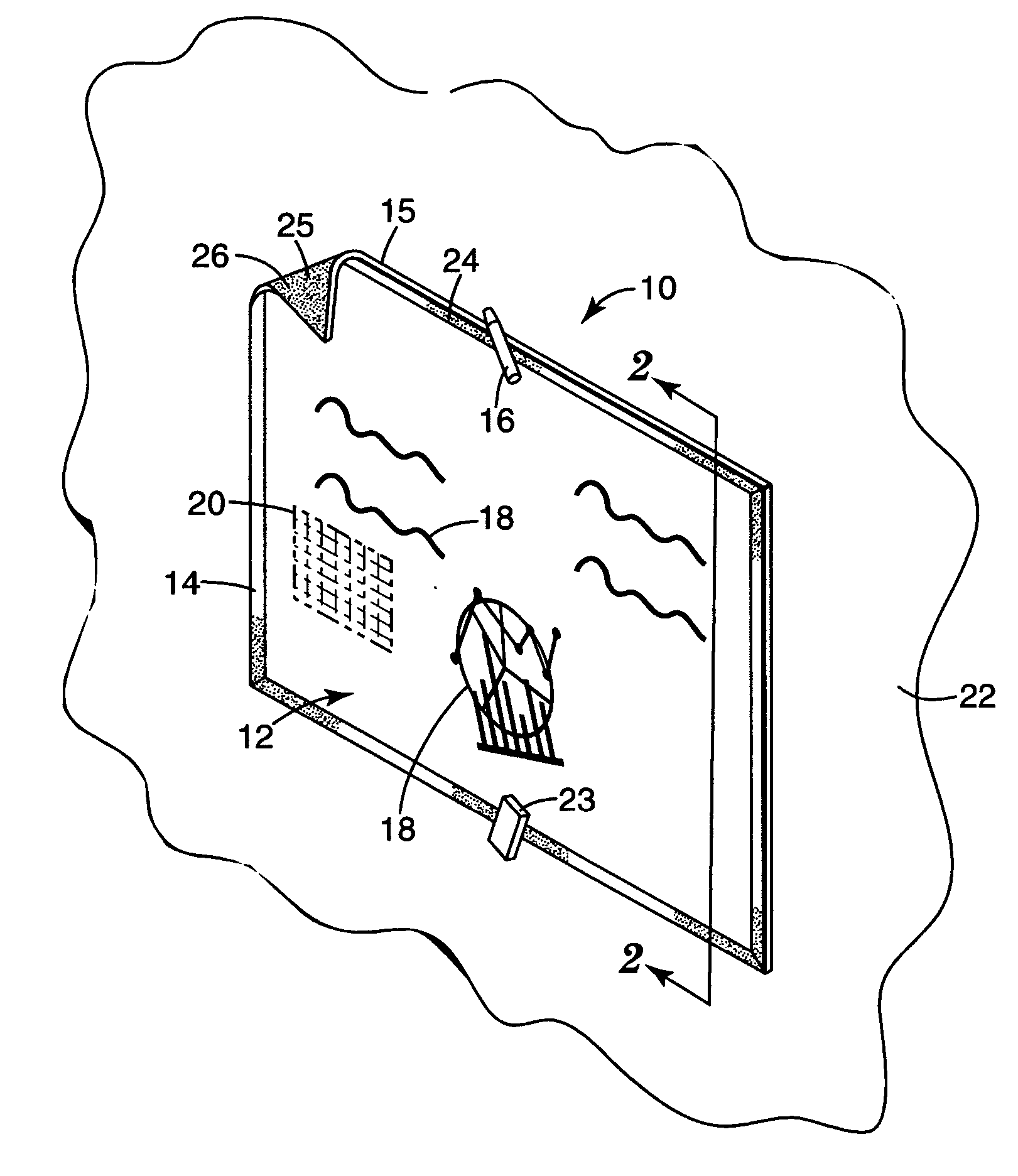
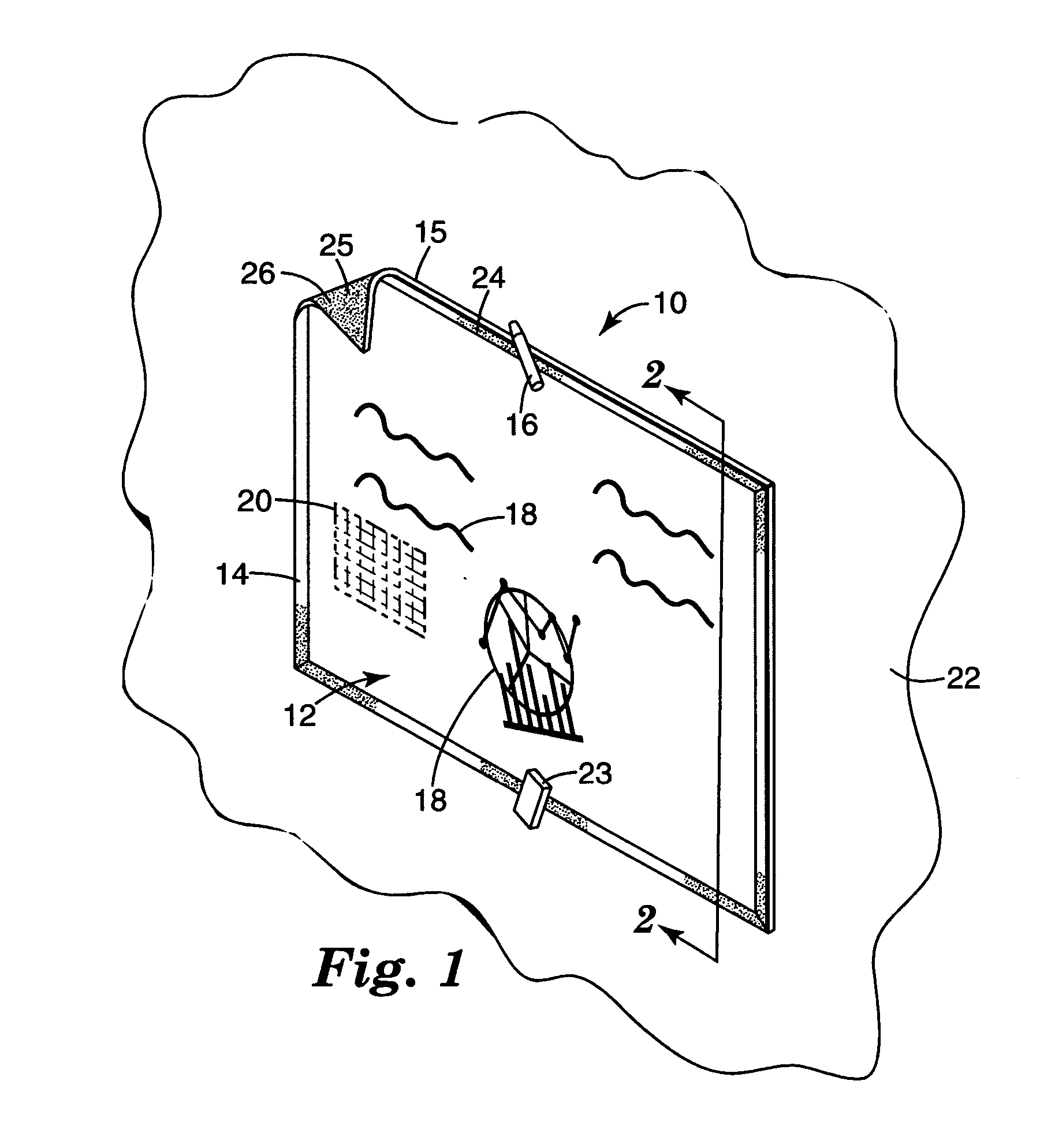
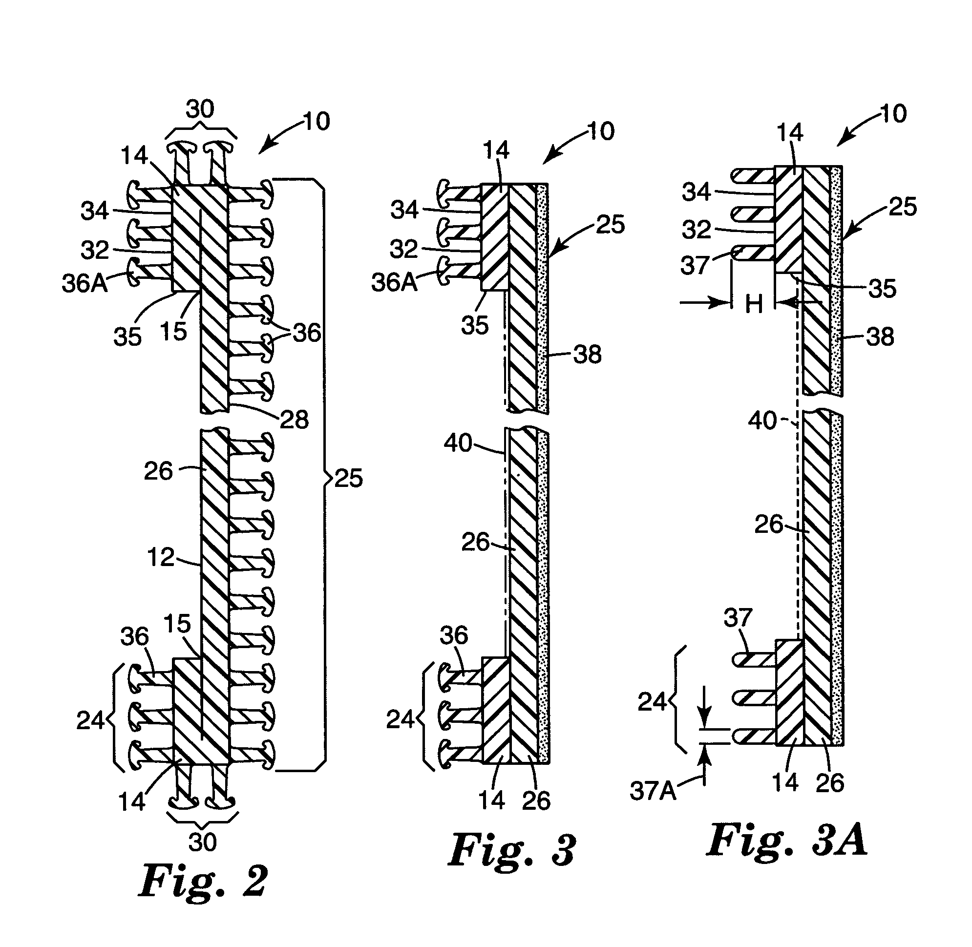
The invention is a display article having a flexible substrate which includes a writing surface capable of being used as a dry erase surface. A peripheral edge extends around the writing surface. A flexible framing strip is affixed to the writing surface at a position proximate to the peripheral edge. One embodiment of the display article can be made by forming a substrate having a writing surface. The substrate defines a periphery edge, a back surface, and a plurality of mushroom shaped hooks extending from the back surface substantially over the entire back surface. The writing surface is capable of being used as a dry erase surface. At least a portion of the periphery of the writing substrate is folded over to form a framing strip having a plurality of exposed mushroom shaped hooks. The framing strip is secured to the writing surface.

Description

CROSS REFERENCE TO RELATED APPLICATION [0001] This application claims the benefit of U.S. Provisional Patent Application No. 60 / 585,014, filed Jul. 2, 2004.BACKGROUND OF THE INVENTION [0002] The invention relates generally to articles having an erasable writing surface. [0003] As commonly used, the term “dry erase” as applied to an article (e.g., a white board) refers to the ability to write or mark on that article with ink (e.g., using a felt tip marking pen), and later erase the ink without the need of a liquid cleaner. In practice, inks intended for use with dry erase surfaces are often specifically formulated for use with individual surface compositions, and may not be useful on all types of dry erase materials. [0004] Dry erase articles are known in the art generally as articles having surfaces that a user may write upon using ink markers. The user may then erase written indicia using an eraser (e.g. a cloth or a felt pad). [0005] Commonly available dry erase substrates (someti...

Claims


Application Information

Patent Timeline
Patent Type & Authority Applications(United States)
IPC IPC(8): B43L1/00
CPCB43L1/00G09F1/12B43L1/10B43L1/08
Inventor HESTER, JONATHAN F.ANNEN, MICHAEL J.HANSEN, BRENT R.QUINN, TIMOTHY L.EMMEL, JOHN J.
Owner 3M INNOVATIVE PROPERTIES CO
Why Eureka
Try Eureka