Holding and positioning apparatus for an optical element

a technology of holding and positioning apparatus, applied in the direction of microlithography exposure apparatus, mountings, instruments, etc., can solve the problems of blurred structures to be imaged in the projection objective of semiconductor lithography during the exposure process, undesired contrast loss, and reduced objective resolution, etc., to achieve the effect of being permissibl

Inactive Publication Date: 2006-01-12
CARL ZEISS SMT GMBH
View PDF29 Cites 20 Cited by
  • Summary
  • Abstract
  • Description
  • Claims
  • Application Information

AI Technical Summary

Benefits of technology

[0012] It is therefore an object of the invention to provide a holding and positioning apparatus for an optical element, in particular for a mirror, with which the disadvantages of the prior art mentioned at the beginning are avoided, the optical element can be positioned exactly and impermissible imaging errors can be compensated.
[0014] The holding and positioning apparatus for the optical element according to the invention suppresses undesired vibration of the optical element by means of a stiff attachment. It is likewise advantageous that, by means of the at least one manipulator unit, the holding and positioning apparatus is additionally able to compensate for the length differences between the optical element and a base body, to which the at least one manipulator unit is connected, in the event of a deviation from the mounting temperature, in order that the forces on the optical element do not become impermissibly high and lead to deformations or even to damage to the optical element. As a result of having solid body joints, it is likewise possible for the irregularities in joint faces to be compensated for without deforming the optical element impermissibly.
[0015] In an advantageous refinement of the invention, three manipulator units can be provided. This holding and positioning apparatus, configured in accordance with the invention, makes it possible to displace the optical element exactly normally with respect to its plane and to tilt it about two mutually independent axes in the plane. Impermissible imaging errors are thus avoided.
[0017] In an advantageous development of the invention, provision can, moreover, be made for at least three sensors to be provided in order to measure lifting and tilting movements of the optical element with respect to a base body. Thus, advantageously, the movement of the optical element during the lifting and tilting adjustment of the optical element can be measured, in order to be able to monitor the magnitude of the lift and the tilt and correct any possible disruptive movement.

Problems solved by technology

If vibration of the deflection mirror occurs, then the structures to be imaged in a projection objective for semiconductor lithography during the exposure process become blurred.
This leads to an undesired loss of contrast and therefore to a reduction in the resolution of the objective.
The disadvantage with the actuator and the lifting and tilting apparatus of U.S. Pat. No. 5,986,827 is the very large amount of space which is required, which results from the separation of bipod and actuating lever.
The disadvantage with such an apparatus is that, as a result of guiding the upper structure by means of the spring elements, the upper structure can be deformed and, as a result of the rectilinear guidance, the angles cannot be compensated.

Method used


Image

  • Holding and positioning apparatus for an optical element
  • Holding and positioning apparatus for an optical element
  • Holding and positioning apparatus for an optical element

Examples


Embodiment Construction

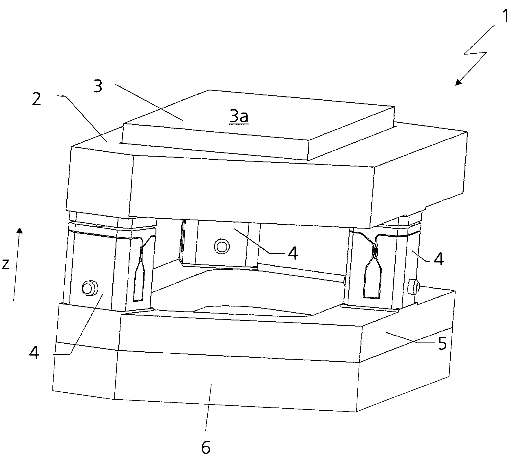
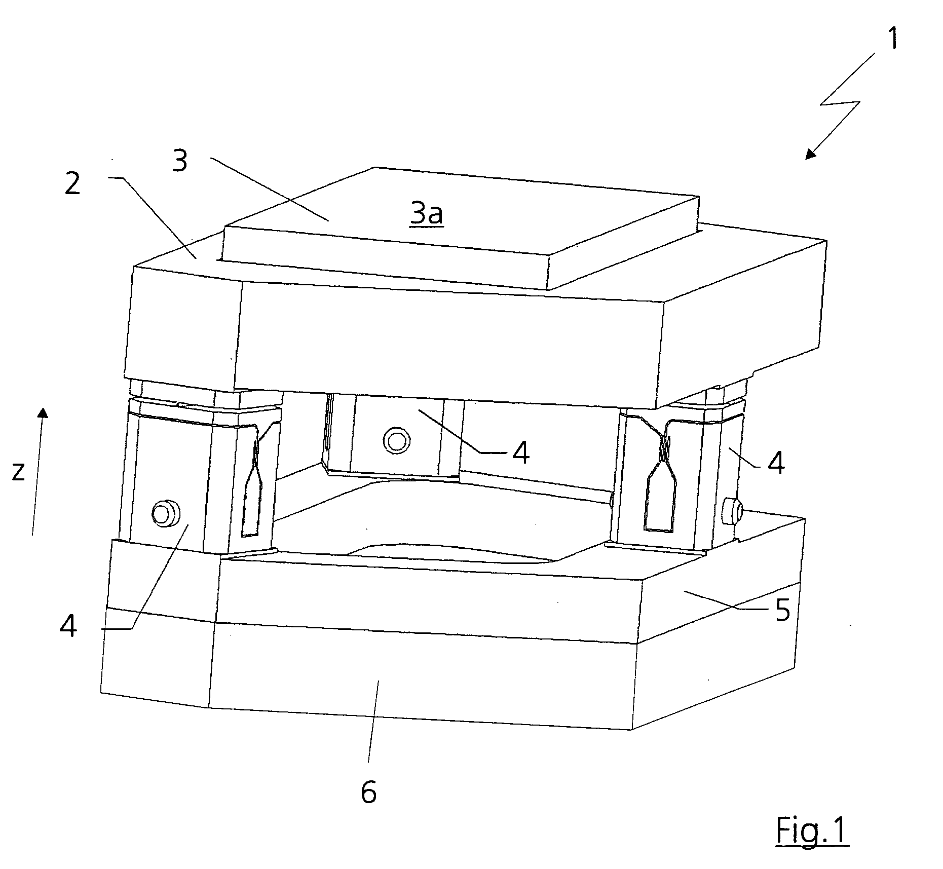
[0030]FIG. 1 shows a holding and positioning apparatus 1 for a projection objective for semiconductor lithography, an optical element 3 being mounted in a mounting ring 2. The optical element 3 is formed as a mirror, preferably as a deflection mirror. The mounting ring 2 is carried and supported by three manipulator units 4, which are firmly connected to a base body 5. The base body 5 is connected in the usual way to a housing (objective housing) or a structure 6. The three manipulator units 4 can be adjusted vertically independently of one another along an optical axis (in the z direction), by which means the mounting ring 2 together with the mirror 3 can be raised at right angles to a mirror plane 3a or tilted about at least one arbitrary axis in the mirror plane 3a.

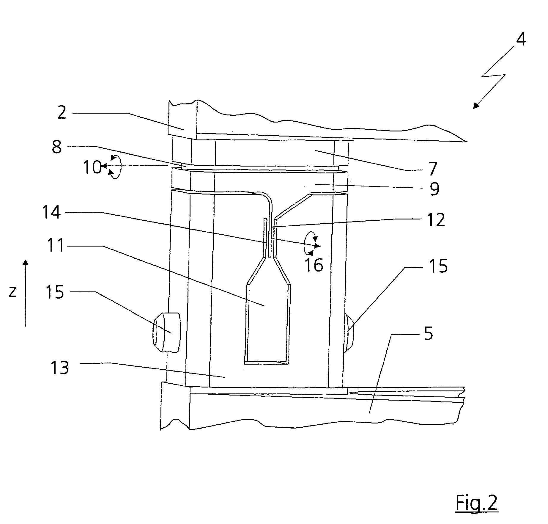
[0031] In FIG. 2, the manipulator unit 4 is illustrated in principle. The manipulator unit 4 has a manipulator head 7 which is connected to the mounting ring 2. The manipulator head 7 is connected to a movable manipul...


PUM

PropertyMeasurementUnit
angleaaaaaaaaaa
angleaaaaaaaaaa
angleaaaaaaaaaa

Abstract

In a holding and positioning apparatus for an optical element, the optical element is mounted in a mounting ring and the mounting ring is mounted via at least one manipulator unit. The manipulator unit has a linear actuating element. The manipulator unit has a manipulator head, a movable manipulator part and a manipulator foot, the manipulator head being connected to the movable manipulator part via a solid body joint. The movable manipulator part is connected to the manipulator foot via an actuator and at least one solid body joint, the linear actuating element being coupled to the manipulator foot and the actuator.

Description

BACKGROUND OF THE INVENTION [0001] 1. Field of the Invention [0002] The invention relates to a holding and positioning apparatus for an optical element, a manipulator unit for moving an optical element and a projection objective for semiconductor lithography. [0003] 2. Description of the Related Art [0004] A projection objective, as disclosed by U.S. 2002 / 0167734 A1, for example, contains a beam splitter and a deflection mirror. While a light beam coming from a reticle is deflected by the beam splitter into a radial arm having a further mirror, the light beam coming from the radial arm is let straight through the beam splitter and deflected by the deflection mirror, parallel to the light beam coming from the reticle, into a further objective region. [0005] In order that the light beam from the radial arm can be deflected into the objective region, it must be possible for the mirror plane of the deflection mirror to be displaced accurately into the point of intersection of the optica...

Claims


Application Information

Patent Timeline
Patent Type & Authority Applications(United States)
IPC IPC(8): G02B7/02G02B7/00G02B7/182G03F7/20
CPCG02B7/003G02B7/1822G03F7/709G03F7/70825G03F7/70833G03F7/70258
Inventor WEBER, ULRICHHOLDERER, HUBERT
Owner CARL ZEISS SMT GMBH
Why Eureka
Try Eureka