Stud alignment jig

Inactive Publication Date: 2006-01-19
GAUTHIER MIKE
View PDF12 Cites 36 Cited by
  • Summary
  • Abstract
  • Description
  • Claims
  • Application Information

AI Technical Summary

Benefits of technology

[0009] In one aspect of the invention, entry to the stud holding portion m

Problems solved by technology

However, wood framing members are more often then not warped or twisted, making it difficult to install said warped studs in perfect alignment.
Although it may be reasonable to assume this device does indeed position the studs generally in their place, it does however fail in many facets; one, that the use of a spring tensioner still allows the warped member to remain warped, two, that it fails to auto-align the plates to the studs, and three

Method used


Image

  • Stud alignment jig
  • Stud alignment jig
  • Stud alignment jig

Examples


Embodiment Construction

[0024] In the following description, similar features in the drawings have been given similar reference numerals.

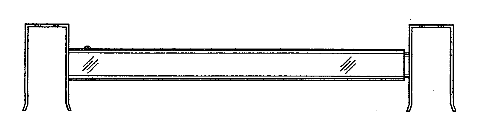
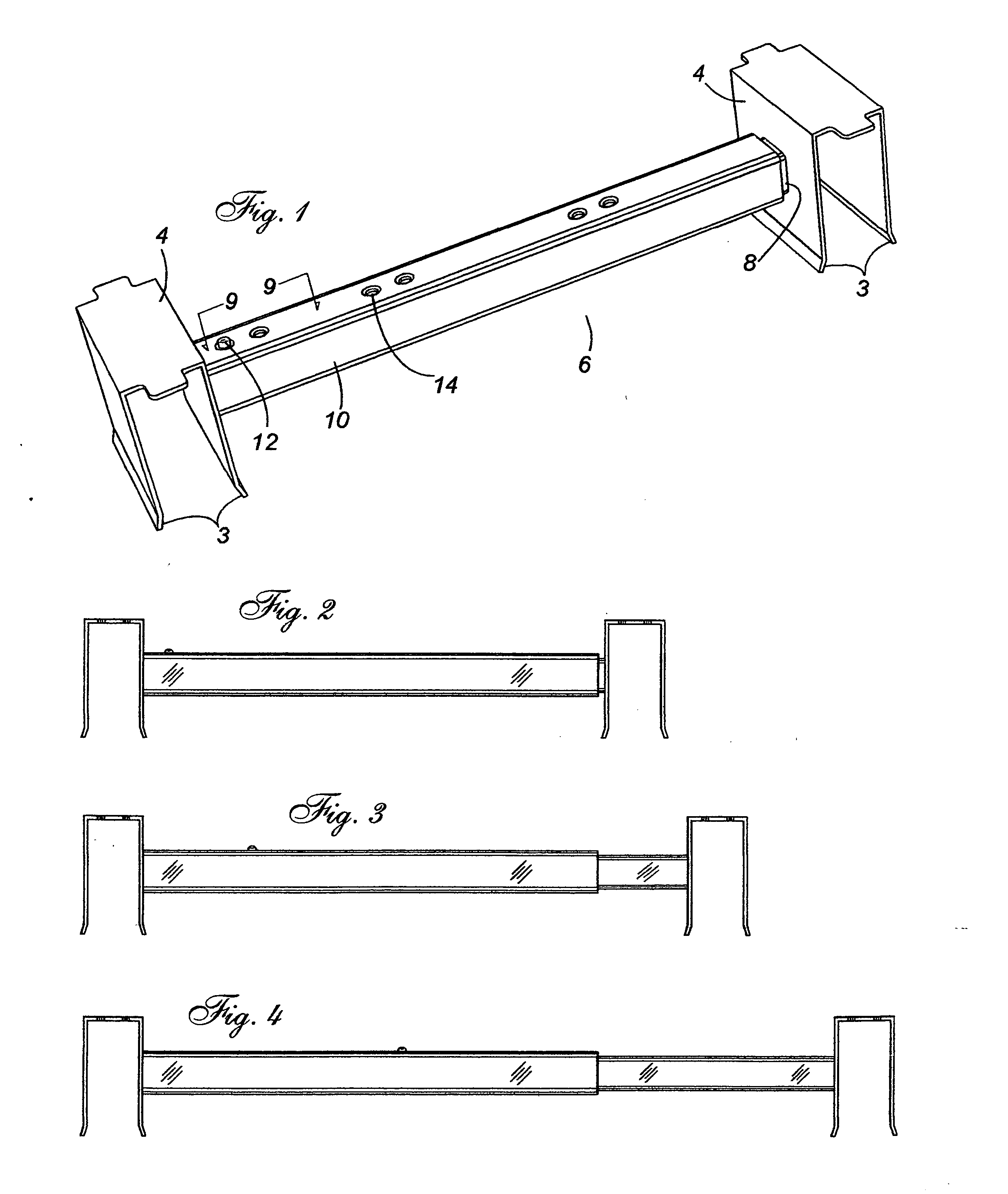
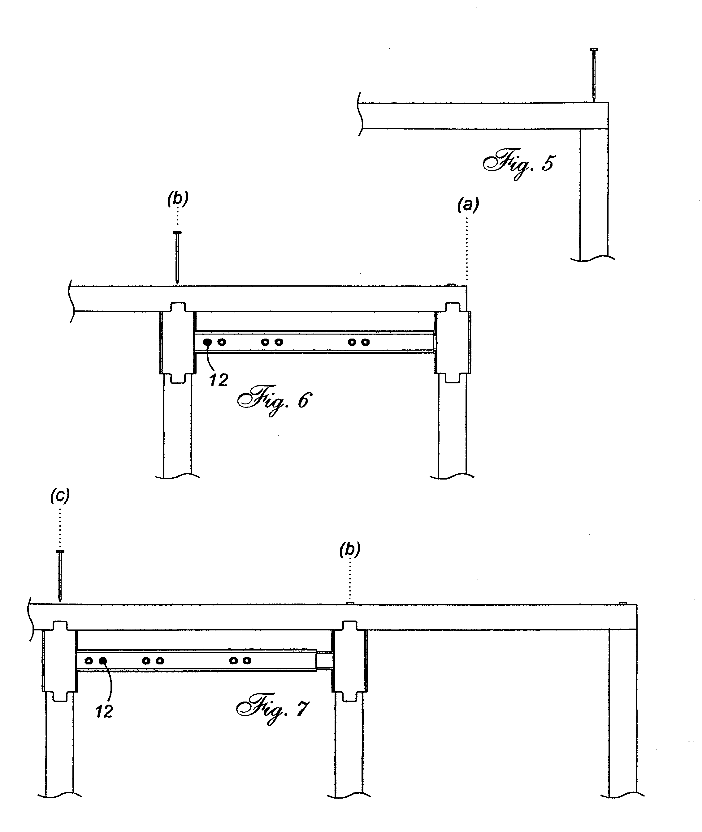
[0025] Turning to the drawings, in particular, FIG. 1, a perspective view from above of the stud alignment jig of the present invention comprising two stud holding end members 4, a central extension portion having an inner tube 8 and an outer tube 10 telescopically engaged to one another wherein said tube members 8 and 10 are fixedly attached to a side portion of a stud holding end member 4 respectively, and a button latch 12 inserted within the inner tube's 8 hollow interior, and protruding a single perforation through said inner tube 8. Therefore, the stud holding end members 4, each attached to one of the inner and outer tubes 8 and 10 respectively can slide longitudinally to each other hence varying the distance between each stud holding end member 4. A plurality of desired spacings can be selected and locked in by depressing the button latch 12 downwardly through a ...


PUM


Abstract

A device that enables speedier wall-stud assembly and accuracy by providing a multi center jig. Three common stud centers include 16″, 19.2″ and 24″. The jig of the present invention comprises; two stud holding end members, a central extension portion having an inner and an outer tube, telescopically engaged to one another wherein each tube member is fixedly attached to a side portion of a stud holding end member. The stud holding end member also incorporates a plate tab, which ensures plate to stud alignment. A wall start setting is also provided for each of the above-mentioned stud centers. A button latch locks the two halves at the desired setting.

Description

FIELD OF THE INVENTION [0001] The present invention relates to a device, which enables speedier wall stud assembly and accuracy by providing a multi center jig. Three common stud centers include 16″, 19.2″ and 24″. The jig of the present invention comprises; two stud holding end members, a central extension portion having an inner and an outer tube, telescopically engaged to one another wherein each tube member is fixedly attached to a side portion of a stud holding end member. The stud holding end member also incorporates a plate tab, which ensures plate to stud alignment. A wall start setting is also provided for each of the above-mentioned stud centers. A button latch locks the two halves at the desired setting. BACKGROUND OF THE INVENTION [0002] It is common for those framing stud walls, to mark the top and bottom plate using a pencil or equivalent marking tool then nail plates to studs. However, wood framing members are more often then not warped or twisted, making it difficult...

Claims


Application Information

Patent Timeline
IPC IPC(8): G01D21/00
CPCE04G21/1891
Inventor GAUTHIER, MIKE
Owner GAUTHIER MIKE
Why Eureka
Try Eureka