Methods and apparatus for sound compensation in an acoustic environment

a technology of acoustic environment and sound compensation, which is applied in the direction of electrical transducers, transducer details, electrical apparatus, etc., can solve the problems of difficult decoding of audio information into understandable speech by the listener's brain, and affecting the listening experien

Inactive Publication Date: 2006-01-19
PEAVEY ELECTRONICS
View PDF5 Cites 15 Cited by
  • Summary
  • Abstract
  • Description
  • Claims
  • Application Information

AI Technical Summary

Benefits of technology

[0010] Aspects of the present invention are directed to simple, operationally intuitive, and automatic methods and apparatus for evaluating and compensating for the sound smear phenomenon in an acoustic environment.

Problems solved by technology

When the sound system is introduced into an acoustic environment, acoustic anomalies are a concern.
Instead, the same sound content arrives from two or more different sources just close enough together (several thousandths of a second) to combine (smear) and make it very difficult for the listener's brain to decode the audio information into understandable speech.
Unfortunately, much of the understandability of human speech is contained in these sibilants and the smearing effect results in little or no intelligibility by the listener even if the talker is speaking at a substantial volume.
This results is sound smear and the attendant un-intelligibility.
The difficulty with achieving satisfactory audio results in a place of worship is compounded by numerous factors, such as poor room design, where multiple sound reflecting surfaces exist.
Another factor affecting audio results is the experience level of the installers who tend to improperly specify and / or install the audio equipment.
This usually leads to less than satisfactory results (for example, sound smear).
While it is possible to achieve satisfactory results using such general purpose audio equipment, it is significantly difficult and complex to achieve satisfactory results given the specific problems presented by some acoustic spaces, such as churches, which have special requirements.
Indeed, these conventional techniques require an array of test equipment, tone sources, meters, oscilloscopes, and sound technicians trained to operated the equipment and perform relatively complex sound measurement and adjustment procedures.

Method used


Image

  • Methods and apparatus for sound compensation in an acoustic environment
  • Methods and apparatus for sound compensation in an acoustic environment
  • Methods and apparatus for sound compensation in an acoustic environment

Examples


Embodiment Construction

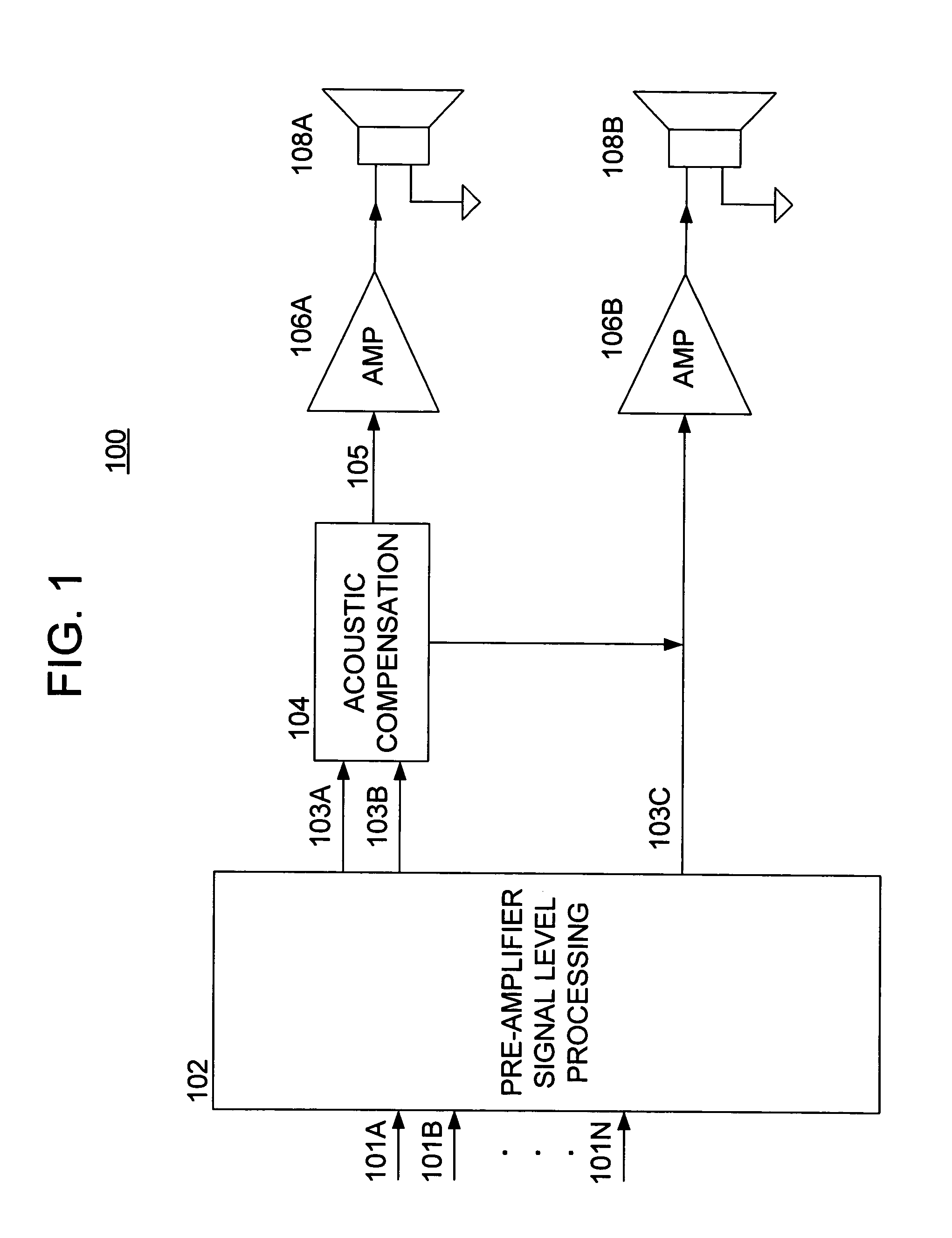
[0027] Referring now to the drawings, wherein like numerals indicate like elements, there is shown in FIG. 1 a block diagram of an audio system 100 in accordance with one or more aspects of the present invention. The basic functionality of the audio system 100 is to compensate for acoustic delays of the sound waves emanating from loudspeakers of the system, which delays cause sound smear.

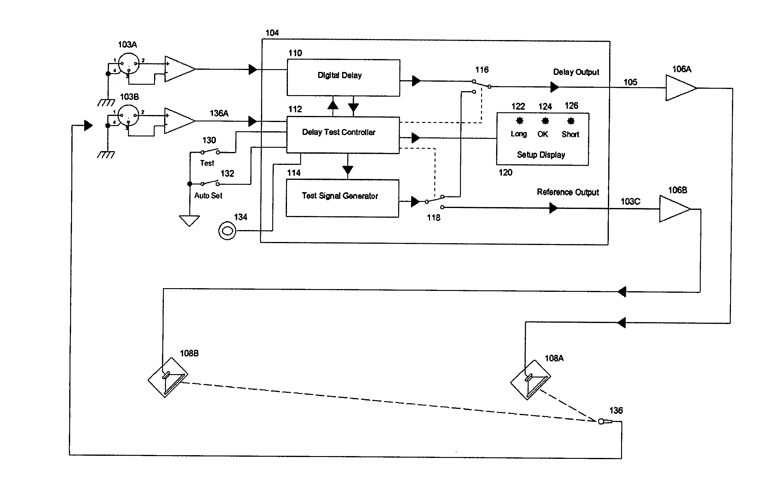
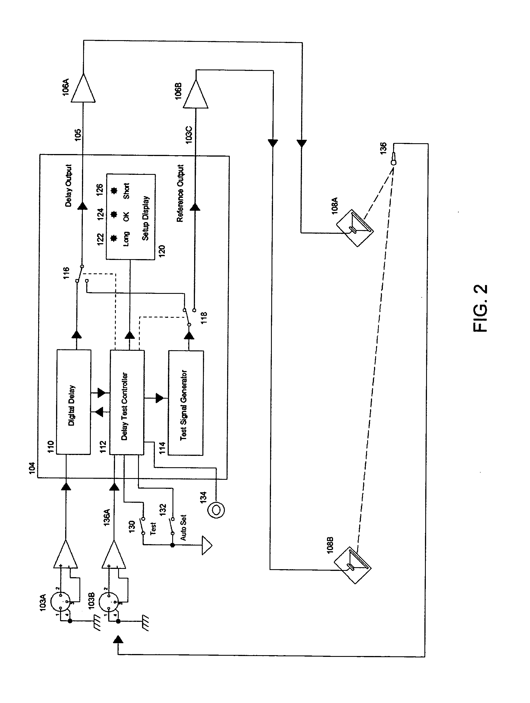
[0028] The system 100 includes a pre-amplifier signal level processing unit 102, and acoustic compensation unit 104, a plurality of amplifiers 106, and a corresponding plurality of loudspeakers 108. As has been discussed hereinabove, one of the loudspeakers 108B represents one or more primary acoustic loudspeakers that are used to originate sound waves into an acoustic space for the enjoyment of an audience. The other loudspeaker 108A represents one or more secondary loudspeakers that are disposed some distance away from the primary loudspeaker 108B, for example, to provide additional sound reinfor...


PUM


Abstract

Methods and apparatus are contemplated for providing a primary audio signal containing audio content to one or more primary loudspeakers; and delaying a secondary audio signal containing the same audio content to one or more secondary loudspeakers, wherein the delay is such that respective sound waves originating from the primary and secondary loudspeakers arrive at a location nearer to the secondary loudspeakers without causing sound smear.

Description

BACKGROUND OF THE INVENTION [0001] The present invention relates to compensating for acoustic problems that arise when sound equipment is used to assist in the amplification of audible content in an acoustic environment. [0002] A typical sound system includes four basic elements, namely one or more microphones, a microphone preamplifier or mixer, a power amplifier and a loudspeaker system. When the sound system is introduced into an acoustic environment, acoustic anomalies are a concern. As the expectations of event-goers have evolved tremendously regarding sound reinforcement, the demands placed on designers / manufacturers of consumer electronics has steadily increased. Everybody expects extremely high quality audio in their cars, home audio and home theatre. Moviegoers expect not only a pleasing visual experience, but also expect a fantastic audio experience. Naturally, this ever increasing level of expectation spills over into virtually every spectator experience, e.g., cinema, au...

Claims


Application Information

Patent Timeline
Patent Type & Authority Applications(United States)
IPC IPC(8): H04R29/00H04R3/00
CPCH04R3/00
Inventor PEAVEY, HARTLEY D.STUCKMAN, THOMAS R.MARKS, STEPHEN J.BELL, JAMES ANDREW
Owner PEAVEY ELECTRONICS
Why Eureka
Try Eureka