Method and device(s) for diagnosis and/or treatment of sleep apnea and related disorders

a technology for sleep apnea and related disorders, applied in the direction of snoring prevention, artificial respiration, sensors, etc., can solve the problems of difficult to distinguish between apnea and hypopnea, inability to quantify, and often unfavorable conditions

Inactive Publication Date: 2014-05-29
YRT
View PDF4 Cites 0 Cited by
  • Summary
  • Abstract
  • Description
  • Claims
  • Application Information

AI Technical Summary

Benefits of technology

[0017]The basic approach herein is to apply an inflatable vest, cuff or other inflatable or pressurizable implement, hereby collectively called VEST, to the external surface of the torso, continuously maintaining a low pressure level in said Vest (holding pressure) to effect close contact between the inner layer of the Vest and the Torso, monitoring flow in and out of th

Problems solved by technology

Although, when conditions are favorable, the signal provides a reasonably good indication of “relative” flow, conditions are frequently unfavorable such as when the nares is blocked or when the patient is breathing through the mouth.
Also, the signal often becomes zero (i.e. signaling no flow), when some flow is still present, making it difficult to distinguish between apneas and hypopneas. b) Thermister: Here, a temperature sensitive sensor is placed in front of the nose and/or mouth.
This signal cannot be quantified and is prone to serious drifts and artifacts, limiting its use to simply distinguish between, flow and no flow. c) Chest and abdomen bands: These are typically applied to the rib cage and abdomen.
These calibrations also change frequently from time to time, making it impractical to use these signals for quantitative evaluation of breathing.
As a result, the use of these bands is currently limited to determining if there are respiratory efforts and whether the rib cage and abdomen move in phase.
Typically, in patients with obstructive apnea this is associated with a ventilatory overshoot (Overshoot) that overcorrects the blood gas changes, inhibiting the Dilators and resulting in another apnea.
This is not well tolerated.
Furthermore, in my experience the inhalation of CO2 approach is difficult to control and often results in sleep disruption.
Negative pressure loading is impractical since it not only req

Method used


Image

  • Method and device(s) for diagnosis and/or treatment of sleep apnea and related disorders
  • Method and device(s) for diagnosis and/or treatment of sleep apnea and related disorders
  • Method and device(s) for diagnosis and/or treatment of sleep apnea and related disorders

Examples


Embodiment Construction

[0045]Design:

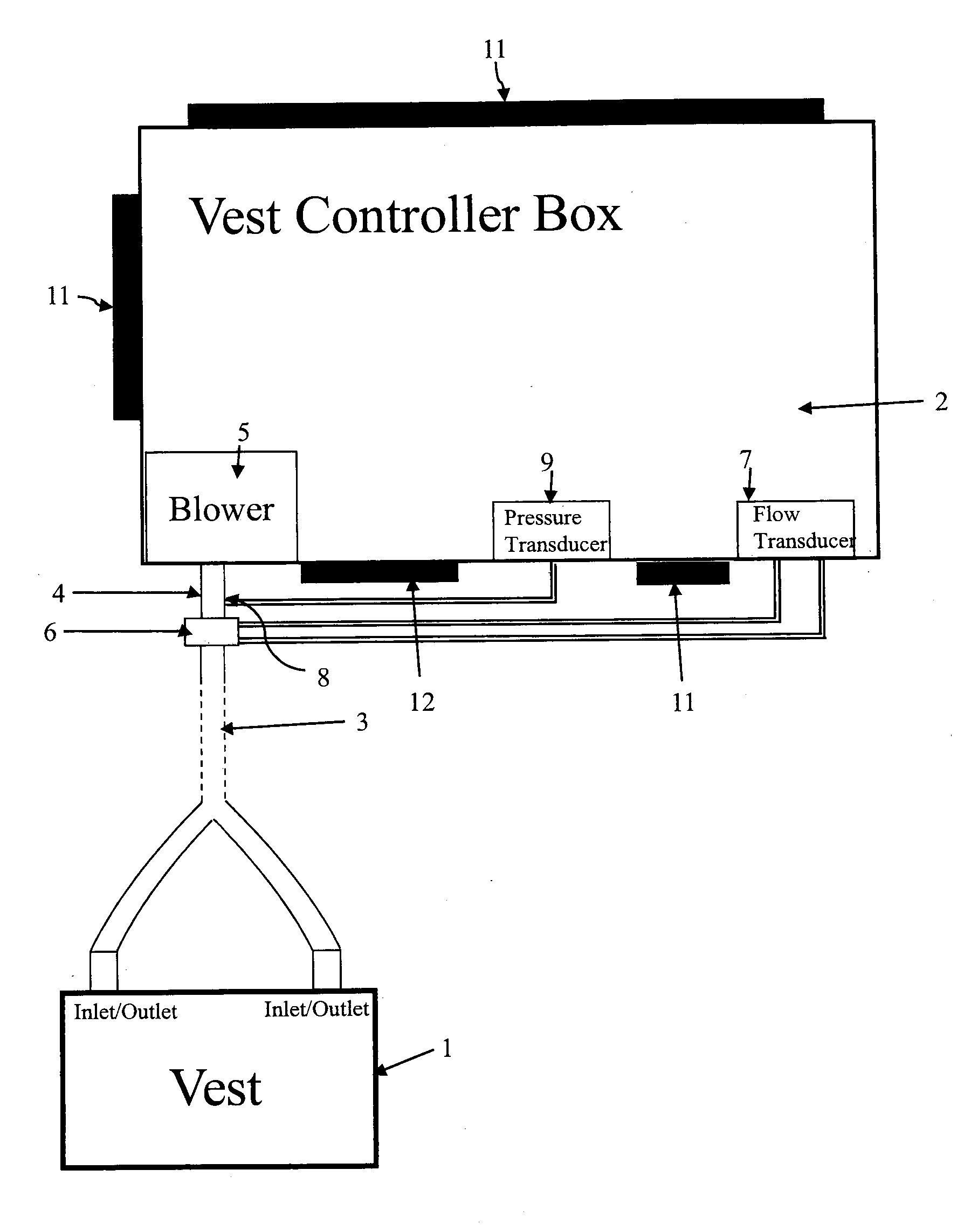
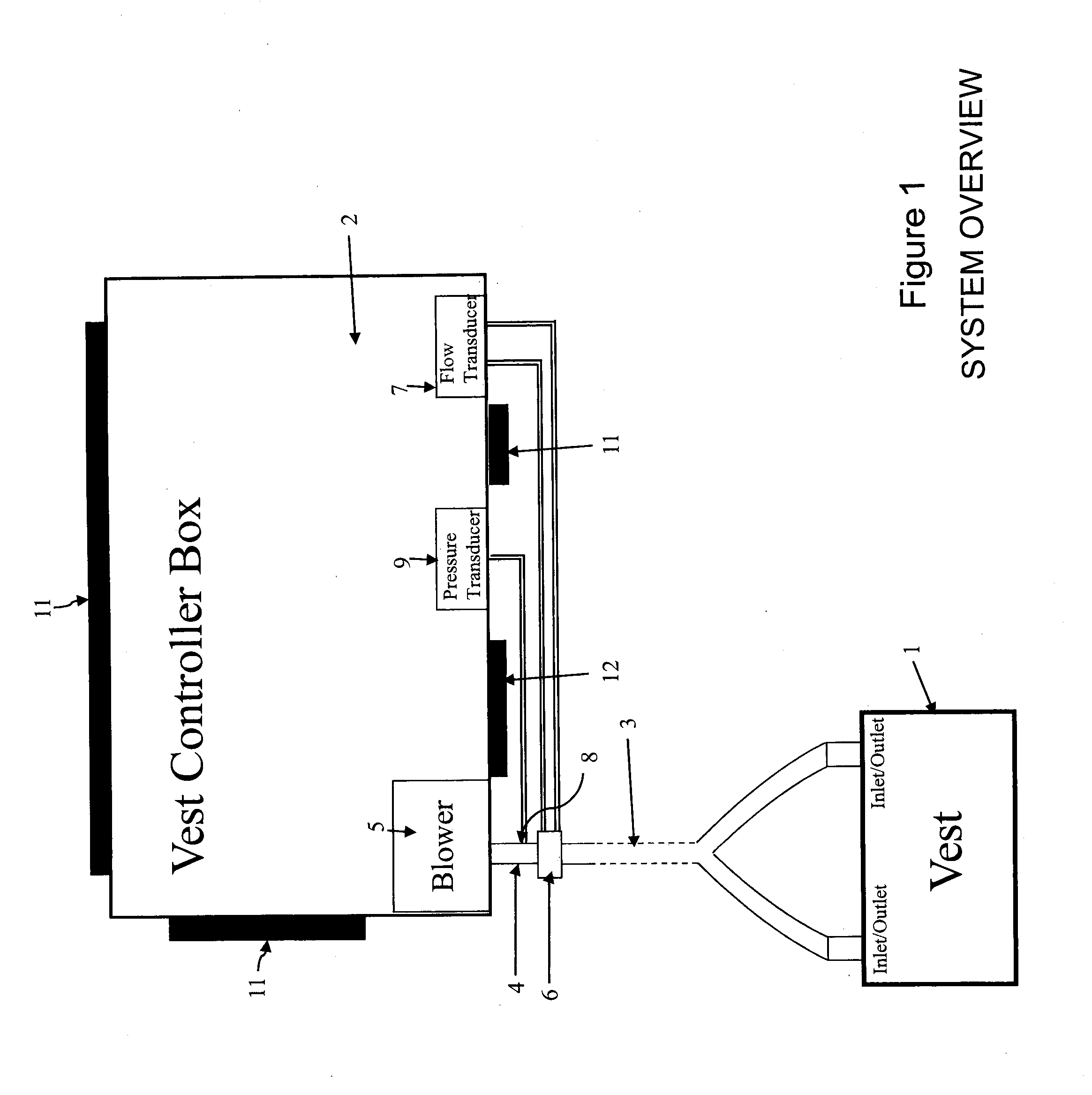
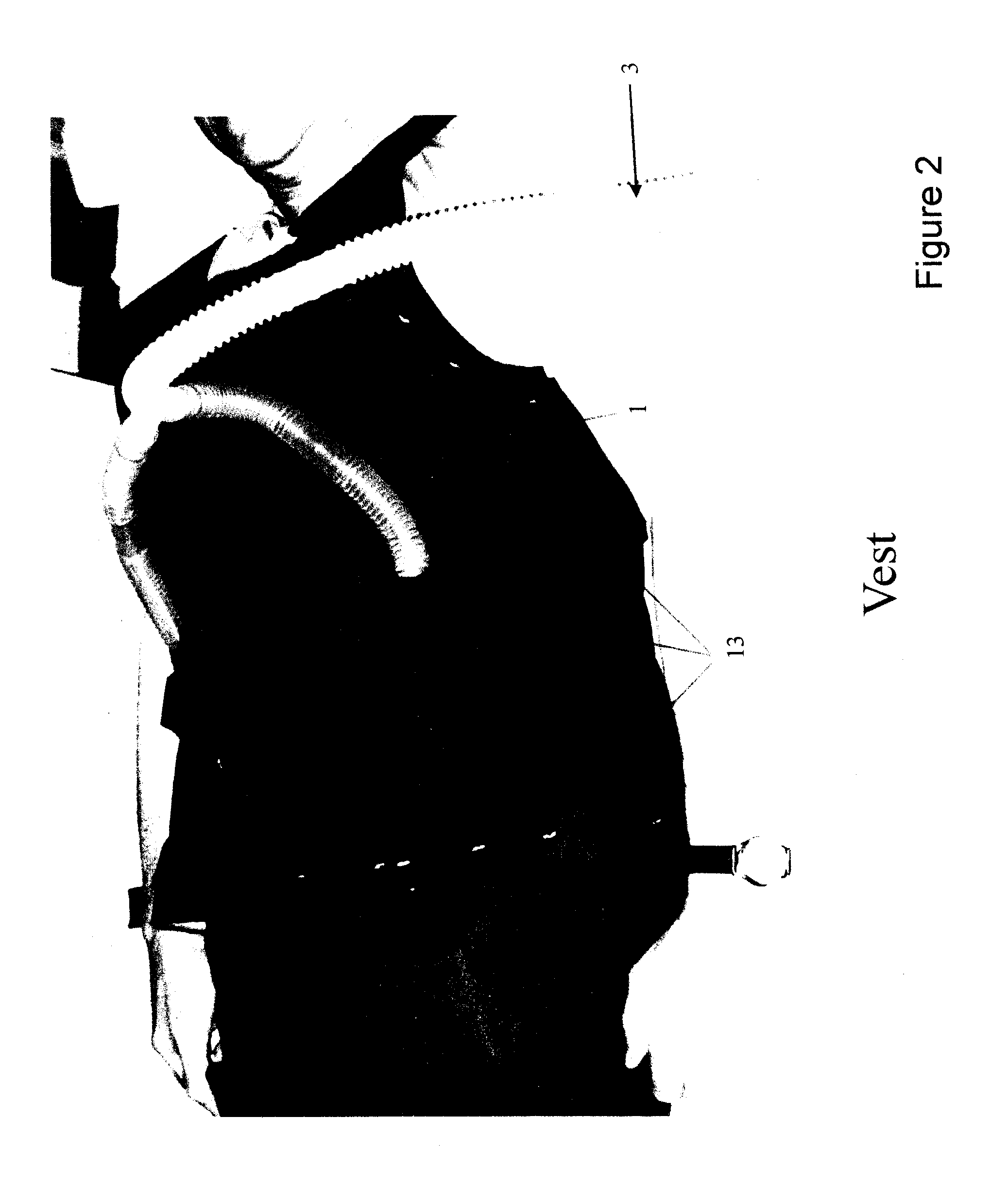
[0046]An overview of the preferred embodiment is shown in FIG. 1. It is comprised of an inflatable vest, a controller box (2) and flexible tubing (3) to connect the inside lumen of the vest (1) to the output (4) of a blower (5) located inside the Controller Box (2). A suitable flow meter (6) is inserted in the tubing (3) close to the Box (2). While a flow meter of any type can be used, we use a Fleisch pneumotachogram and connect its two ports to the two ports of a differential pressure transducer (7) inside the box. A small port (8) in the tubing (3) is connected to a port of another pressure transducer (9) inside the Box (2) to measure tubing pressure. Although the flow meter (6), pressure port (8) and their connections are located outside the Box (2) in this embodiment, they can optionally be located inside the Box (2). A number of control knobs (11) are located on the front, side and back of the box (FIGS. 7 to 9). Additionally, analog input / output sockets (12) are ...


PUM


Abstract

Method and device for diagnosing and/or treating sleep apnea and related sleep disorders, such as snoring and respiratory effort-related arousals, includes an inflatable implement which is applied to the external surface of the chest and/or abdomen (Vest). Pressure is caused to rise to a predetermined positive value. The rate of airflow into and/or out of said Vest is monitored, whereby the Vest Flow is displayed or processed to obtain information about the breathing characteristics of the patient.

Description

FIELD OF INVENTION[0001]The present invention concerns a common approach to the diagnosis and treatment of sleep apnea and related disorders, such as Snoring and Respiratory Effort Related Arousals, that consists of applying positive pressure to the external surface of the chest and / or abdomen during part or all of the respiratory cycle, by use of an inflatable vest or cuff, in order to: a) make intra-thoracic pressure less negative during inspiration and / or b) make intra-thoracic pressure more positive during expiration and / or c) to slightly increase Vest pressure on a continuous basis. In applications a) and b) the system is intended to treat the Sleep-related disorders. In application c), the system is intended to simply monitor breathing in order to help diagnose these disorders. The diagnostic and therapeutic modes can be embodied in single or independent devices depending on intended use.BACKGROUND TO THE INVENTION[0002]Sleep Respiratory Disorders are disorders in which the fl...

Claims


Application Information

Patent Timeline
IPC IPC(8): A61B5/00A61B5/08A61F5/56A61H9/00
CPCA61B5/4818A61B5/0816A61H9/0092A61B5/6805A61F5/56A61B5/4836A61B5/08A61B5/4815A61H31/00A61H2201/0103A61H2201/165A61H2201/5007A61H2201/5071A61H2201/5087A61H2205/08A61H2230/405A61H2230/505A61B5/1135
Inventor YOUNES, MAGDY
Owner YRT
Why Eureka
Try Eureka