Method for removing hydrogen sulphide and other acidic gas components from pressurized technical gases

a technology of acidic gas and pressurized gas, which is applied in the direction of liquid separation agent, inorganic chemistry, separation process, etc., can solve the problems of high investment cost of compressors and the energy required for tail gases compression

Inactive Publication Date: 2011-08-30
UHDE GMBH
View PDF31 Cites 4 Cited by
  • Summary
  • Abstract
  • Description
  • Claims
  • Application Information

AI Technical Summary

Benefits of technology

[0023]The advantage of the invention is that the tail gas leaving the Claus process need not be compressed to a high pressure since a gas scrubbing unit operating selectively with regard to hydrogen sulphide and carbon dioxide already encompasses enrichment columns specific to the individual gas components and operated at a low pressure level. Hence the tail gas can be tied in at the most suitable point without any change to the fringe conditions of the regeneration or absorption units.
[0024]A further advantage of the invention is that the integration of the tail gas into the flash column permits the production of a CO2 enriched regeneration gas with very low CO concentration in the downstream column operated with regeneration carrier gas.

Problems solved by technology

The first disadvantage to be considered is the compression energy required for the tail gases, which is related to the high investment costs for compressors in order to cope with the rise in quasi atmospheric pressure to the 20-60 bar pressure of the main stream and specifically, the rise in pressure in the case of tail gas streams of small volumes and the choice of the adequate compressor type which must meet any operational requirement, for instance, that of existing traces of elemental sulphur.
In the second case, the disadvantage lies with the fact that the regeneration gas coming from the non-thermal regeneration column has a concentration that does not permit a non-polluting release of this stream into the atmosphere.

Method used


Image

  • Method for removing hydrogen sulphide and other acidic gas components from pressurized technical gases
  • Method for removing hydrogen sulphide and other acidic gas components from pressurized technical gases

Examples


Embodiment Construction

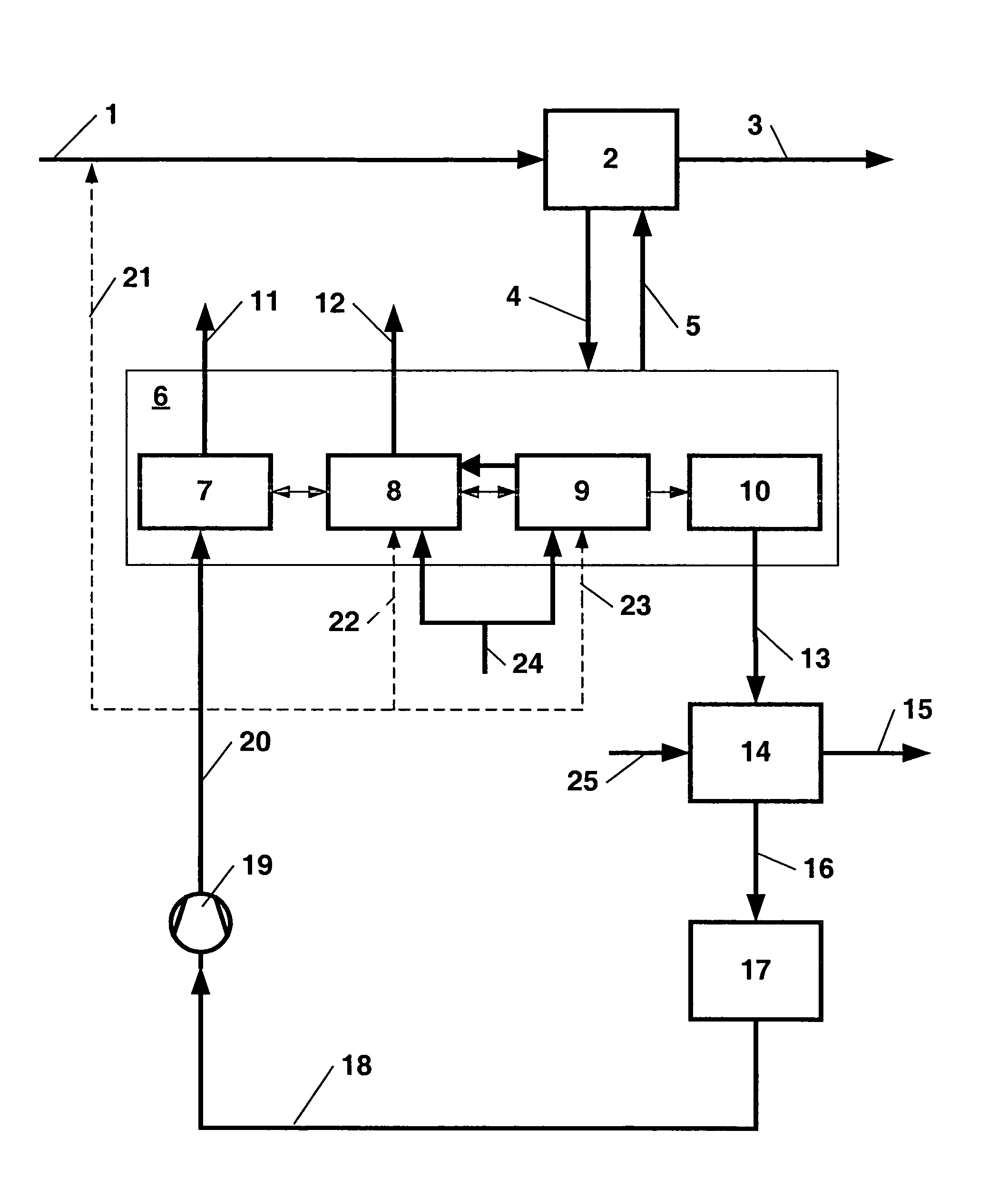
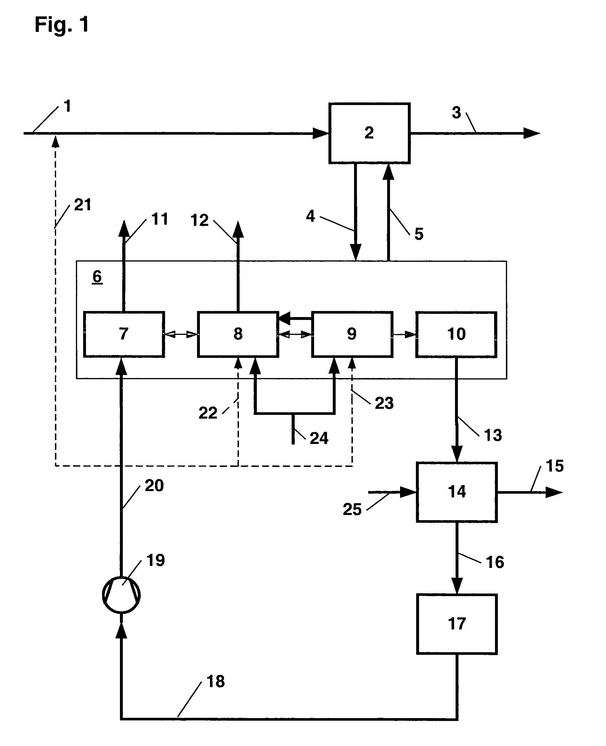
[0026]Feed gas 1 with a pressure of 32.8 bars is piped to absorption unit 2 in which hydrogen sulphide and sour gas components such as CO2 are removed. Cleaned product gas 3 leaves absorption unit 2. Laden absorbent 4 is sent to multi-stage regeneration unit 6 encompassing flash column 7, H2S enrichment device 8, CO2 stripping device 9 and thermal regeneration unit 10, it is regenerated there and then recycled as regenerated absorbent 5 to absorption unit 2. Nitrogen 24 is piped to H2S enrichment device 8 and CO2 stripping device 9. Sour gas streams 11 and 12 contain sour gas components, in particular CO and CO2 and inert gas in various chemical compositions, are free of or poor in sulphur components and suitable for further processing in other plant units. Sour gas stream 12 is especially poor in CO and thus suitable for a complete or partial release into the atmosphere.

[0027]Claus gas 13 separated in thermal regeneration unit 10 and laden with hydrogen sulphide as well as air 25 a...


PUM

PropertyMeasurementUnit
pressuresaaaaaaaaaa
pressureaaaaaaaaaa
atmospheric pressureaaaaaaaaaa

Abstract

The invention relates to a method for removing hydrogen sulphide and other acidic gas components from pressurized technical gases by means of a physical detergent and for obtaining sulphur from hydrogen sulphide by using a Claus system. The hydrogen sulphide and the other acidic gas components are removed in an absorbent manner from the physical detergent, the physical detergent undergoes multi-step regeneration, said multi-step regeneration comprising at least one device for CO enrichment, a device for H2S enrichment, a device for CO2 stripping and a device for thermal regeneration. The various regeneration steps consist of various pressure steps and have a lower pressure than that of the absorption. A hydrogen sulphide rich Claus gas is withdrawn from one of the regeneration steps and is guided to a Claus system where sulphur is produced. The residual gas exiting from the Claus system is hydrated and is condensed under pressure, corresponding to one of the regeneration steps. The condensed residual gas is guided into said device which is used for CO enrichment. Said device for CO enrichment can be embodied as a flash column.

Description

BACKGROUND OF THE INVENTION[0001]The invention relates to a process for the removal of hydrogen sulphide and other sour gas components from industrial gases under pressure by means of physical scrubbing agents, to the recovery of sulphur from hydrogen sulphide using a Claus plant and to the reduction of CO emissions.[0002]Sulphur components are selectively removed from industrial gases at elevated pressures (20 to 60 bar) using physically acting absorbents such as Rectisol, Selexol, Genosorb, Morphysorb, with due consideration for the potential presence of CO2. Apart from the gas stream cleaned, the regeneration process also produces two regeneration gas streams at low pressure (1 to 3 bars) which contain the sour gas components removed: one stream laden with hydrogen sulphide and originating from a thermal regeneration column, one stream (or several streams) laden with carbon dioxide but almost free of hydrogen sulphide traces and originating from a non-thermal regeneration column,...

Claims


Application Information

Patent Timeline
Patent Type & Authority Patents(United States)
IPC IPC(8): B01D53/14B01D53/52C01B17/04C01B17/16
CPCB01D53/1418B01D53/1425B01D53/1462B01D53/526C01B17/0408C01B17/167Y02P20/151
Inventor SAECKER, GEORGMENZEL, JOHANNES
Owner UHDE GMBH
Why Eureka
Try Eureka