Method for suctioning liquid fuel from a liquid trap in a fuel tank; and fuel system for a motor vehicle

a technology of liquid fuel and fuel tank, which is applied in the direction of liquid fuel feeders, combustion air/fuel air treatment, machines/engines, etc., can solve the problems of ejector pumps that are not pressure sensitive, may not properly function, and permanently consume energy

Active Publication Date: 2015-11-26
AUDI AG
View PDF8 Cites 6 Cited by
  • Summary
  • Abstract
  • Description
  • Claims
  • Application Information

AI Technical Summary

Benefits of technology

[0021]It is also advantageous when the capacity of the liquid trap or the collection container is adjusted to the maximum amount of liquid fuel generated during a hot dynamic drive and / or when an expansion volume is provided in a vent line leading from the liquid trap to the filler plug or filler tube of the fuel tank to ensure a low pressure level in the liquid trap.
[0022]When a connection is present between the filler plug or filler tube of the fuel tank and the liquid trap, a valve may advantageously be provided at the connection, which prevents a reverse suctioning of fuel from the filler tube into the liquid trap during emptying of the liquid trap. The valve preferably has three ports of which a first port communicates with the liquid trap, a second port with the filler plug or filler tube and a third port with the environment. The valve is designed so that on the one hand air can flow through the valve into the liquid trap when a negative pressure exists within the liquid trap and on the other hand gas or a gas mixture displaced through the liquid trap during refueling is conducted through the valve to the filler plug or filler tube.

Problems solved by technology

However, ejector pumps have several drawbacks.
For example ejector pumps are pressure-sensitive and may not properly function in the case of a pressure decrease or pressure regulation in the fuel tank.
They are also permanently consuming energy without significantly emptying the collection container and also require a complex construction to avoid leakages and an entering of fuel into the at least temporarily submerged liquid traps.

Method used


Image

  • Method for suctioning liquid fuel from a liquid trap in a fuel tank; and fuel system for a motor vehicle
  • Method for suctioning liquid fuel from a liquid trap in a fuel tank; and fuel system for a motor vehicle
  • Method for suctioning liquid fuel from a liquid trap in a fuel tank; and fuel system for a motor vehicle

Examples


Embodiment Construction

[0032]Throughout all the Figures, same or corresponding elements are generally indicated by same reference numerals. These depicted embodiments are to be understood as illustrative of the invention and not as limiting in any way. It should also be understood that the drawings are not necessarily to scale and that the embodiments are sometimes illustrated by graphic symbols, phantom lines, diagrammatic representations and fragmentary views. In certain instances, details which are not necessary for an understanding of the present invention or which render other details difficult to perceive may have been omitted.

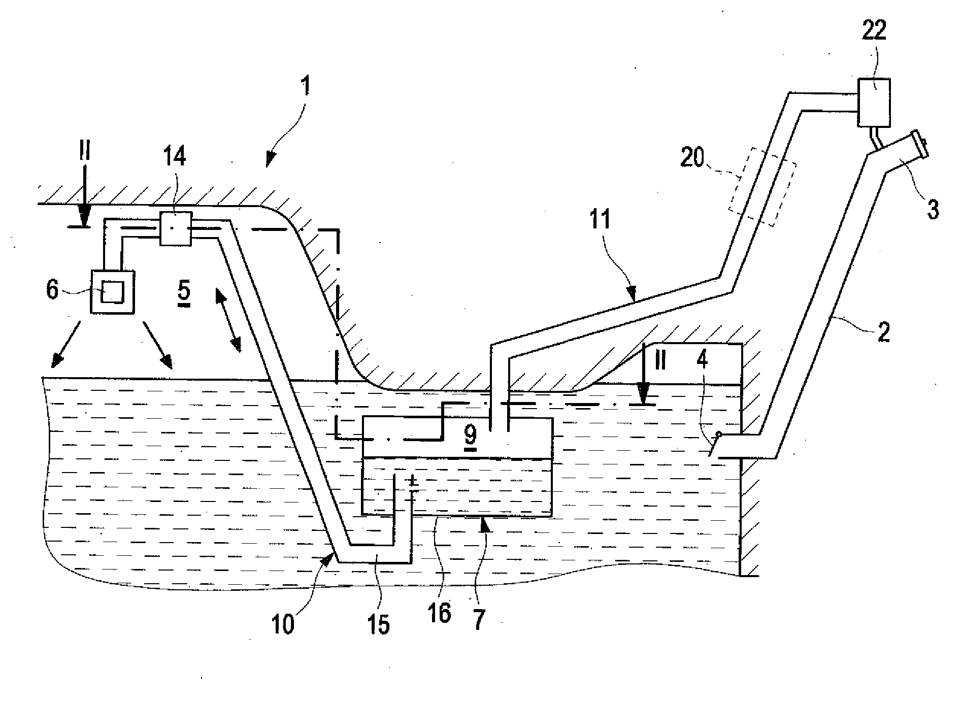
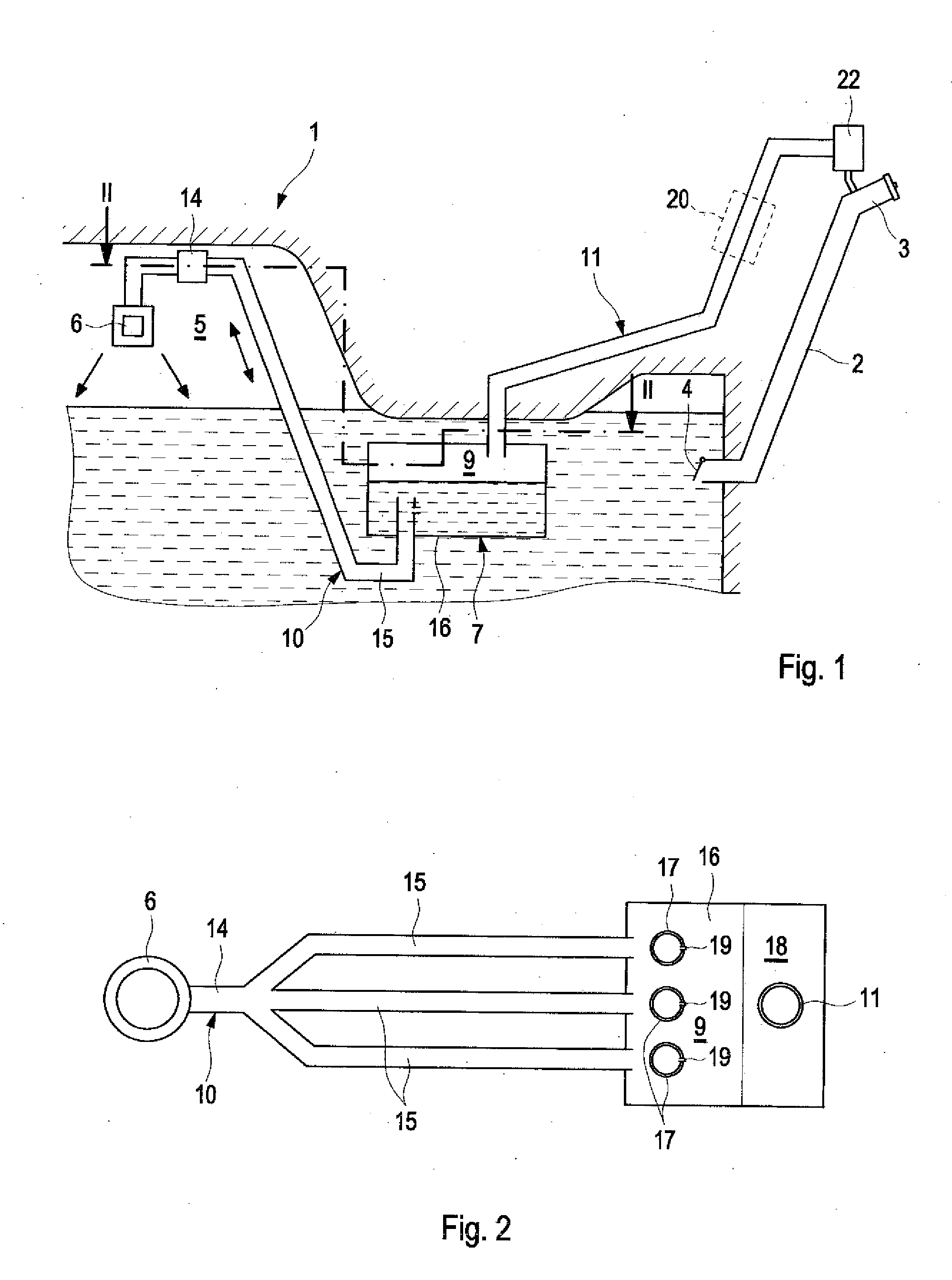
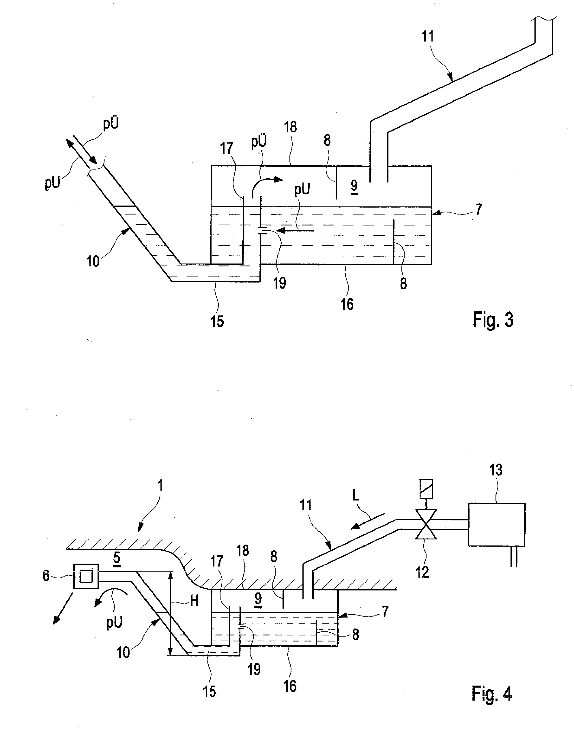
[0033]The fuel system, which is only partially shown in the Figures, is intended for a motor vehicle with internal combustion engine. The fuel system includes a pressure-tight fuel tank 1, which is provided with a filler tube 2 for refueling, a pressure-tight lockable filling plug 3 and a flap 4 at its lower end.

[0034]The fuel tank 1 is provided with a tank venting device that...


PUM


Abstract

A method for suctioning liquid fuel from a liquid trap in a fuel tank of a motor vehicle, includes generating a negative pressure in a gas compartment or headspace of the fuel tank, applying the negative pressure to the liquid trap through a suction line, wherein the liquid trap has a collection container collecting liquid fuel during venting of the fuel tank, and at least partially suctioning the liquid fuel located in the collection container through the suction line into the gas compartment or headspace.

Description

CROSS-REFERENCES TO RELATED APPLICATIONS[0001]This application claims the priority of German Patent Application, Serial No. 10 2014 007 694.6, filed May 23, 2014, pursuant to 35 U.S.C. 119(a)-(d), the disclosure of which is incorporated herein by reference.BACKGROUND OF THE INVENTION[0002]The invention relates to a method for suctioning liquid fuel from a liquid trap in a fuel tank of a motor vehicle, in which liquid fuel is separated and collected in a collection chamber during ventilation of the fuel tank. The invention further relates to a fuel system for a motor vehicle, including a fuel tank, a liquid trap situated in the fuel tank for separating liquid fuel during ventilation of the fuel tank, wherein the liquid trap includes a collection chamber for the extracted fuel.[0003]The following discussion of related art is provided to assist the reader in understanding the advantages of the invention, and is not to be construed as an admission that this related art is prior art to t...

Claims


Application Information

Patent Timeline
Patent Type & Authority Applications(United States)
IPC IPC(8): F02M33/04
CPCF02M33/04F02M33/08B60K15/03504B60K2015/03509B60K2015/03514F02M33/02F02M37/0082
Inventor HAGEN, HARALD
Owner AUDI AG
Why Eureka
Try Eureka