Air fuel ratio control apparatus for engines

a technology of air fuel ratio and control apparatus, which is applied in the direction of electric control, fuel injection control, machines/engines, etc., can solve the problems of large increase in size, complexity, weight and cost, and difficulty in connecting this apparatus to all engines, and achieves a large control unit capacity, low co concentration, and superior heat resistance properties.

Inactive Publication Date: 2005-10-27
ZAMA JAPAN
View PDF9 Cites 11 Cited by
  • Summary
  • Abstract
  • Description
  • Claims
  • Application Information

AI Technical Summary

Benefits of technology

[0008] In order to achieve the technical advantage described above, in accordance with the present invention, an air fuel ratio control apparatus of an engine comprises a fuel control member placed in a fuel passage delivering fuel from a fuel metering chamber of a carburetor supplying the fuel to a suction passage of a comparatively small engine, such as a general purpose engine, a working machine engine, and the like; a combustion gas sensor placed in communication with an engine exhaust, e.g., in an exhaust pipe, of the engine; and an electronic control unit, wherein the control unit actuates the fuel control member in response to a concentration of a combustion gas component in an exhaust gas detected by the combustion gas sensor so as to control a fuel flow rate.
[0009] A precise air fuel ratio control is not always necessary in order for the general purpose engine to satisfy the emission requirements, and if the concentration of the harmful component is within a numeric range of the emission requirements, the emission requirements may be satisfied. The present invention is structured to detect a concentration of an optional specific component, e.g., carbon monoxide (hereinafter “CO”), in the combustion gas. CO is identified as a harmful component when contained in the exhaust gas and may be detected by using the combustion gas sensor which is inexpensive in comparison with the O2 sensor. The control unit actuates the fuel control member so as to dilute the air-fuel mixture in order to lower the concentration of CO, thereby controlling the fuel flow rate. Accordingly, it is possible to control the air fuel ratio so as to satisfy the emission requirements without using the known and relatively expensive O2 sensor and the three-way catalyst and by using the large capacity of control unit.
[0010] In this case, as the combustion gas is detected and diluted in the present invention, the harmful component may be carbon monoxide, hydrogen, carbon hydride, sulfur dioxide, nitrogen dioxide, or the like.
[0011] Further, in accordance with the present invention, the air fuel ratio control apparatus may be used in a forcibly air-cooled engine in which an engine is provided with a cooling fan, comprising: a fuel control member disposed in a fuel passage delivering fuel from a fuel metering chamber of a carburetor and supplying fuel to a suction passage of the general purpose engine; an air delivery path introducing a portion of a discharged air for the cooling fan to an exhaust pipe of the general purpose engine; a combustion gas sensor disposed in a downstream side of an air delivery path connection position in an exhaust pipe; and an electronic control unit, wherein the control unit actuates the fuel control member in correspondence with a concentration of a combustion gas component in an exhaust gas detected by the combustion gas sensor so as to control a fuel flow rate.
[0012] Many combustion gas sensors have a low concentration range for detecting gas concentration and are inferior in a heat resisting properties. The present invention lowers the concentration of the harmful component to a detectable range by mixing a portion of the air for air cooling to the exhaust gas, and widens a usable range of choice of the combustion gas sensor by lowering an exhaust gas temperature to a usable temperature range.
[0013] Further, in order to achieve the technical advantages of the present invention, it is preferable that a CO sensor is used as the combustion gas sensor, and an electromagnetic valve is used as the fuel control member. It is known that of the harmful components in the exhaust gas, CO is contained at the largest quantity and may attain a maximum concentration of about 10% in a high concentration region of the air-fuel mixture without relation to a size or output of the engine, and becomes about 1% in a lean region at a position near the theoretical air fuel ratio. Accordingly, it is effective for achieving the desired technical advantage of the invention to detect the concentration of CO in the exhaust gas by using the CO sensor and to close the opening and closing valve so as to reduce the concentration of CO to satisfy an emission requirement compliance range. Further, if a normally open-type electromagnetic valve is used as the electromagnetic valve, the fuel passage is left open at a time when the valve is not operated due to a disconnection or the like. Accordingly, it is possible to maintain a normal function as the carburetor so as to continue an engine operation.

Problems solved by technology

Because of these additional capacities, the apparatus increases greatly in size, complexity, weight, and cost.
Accordingly, it is difficult to connect this apparatus to all engines, for example, a general purpose engine which requires a compact size, a reduced weight, and an easy handling properties, such as in portable, working machines or the like.
Nevertheless, because this structure does not take into direct consideration the detection of an actual state of the exhaust gas so as to satisfy emission requirements, this structure is not a complete solution to the presented problem.

Method used


Image

  • Air fuel ratio control apparatus for engines
  • Air fuel ratio control apparatus for engines

Examples


Embodiment Construction

[0018] A description is given of an embodiment in accordance with the present invention with reference to the accompanying figure.

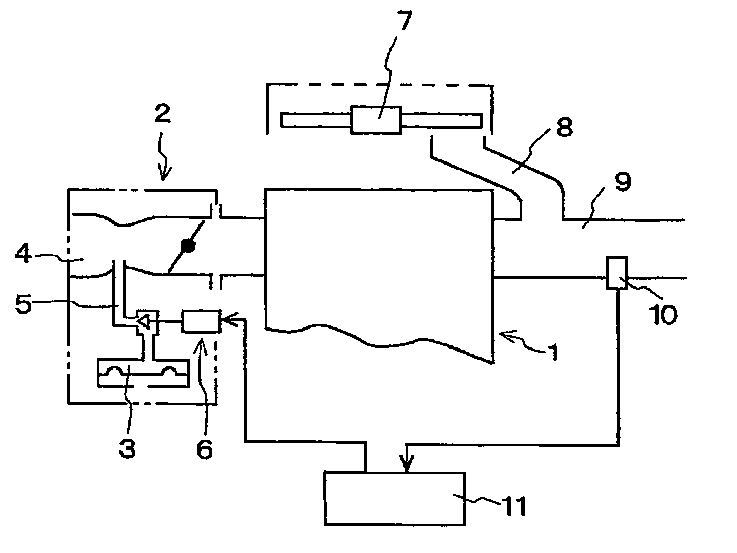
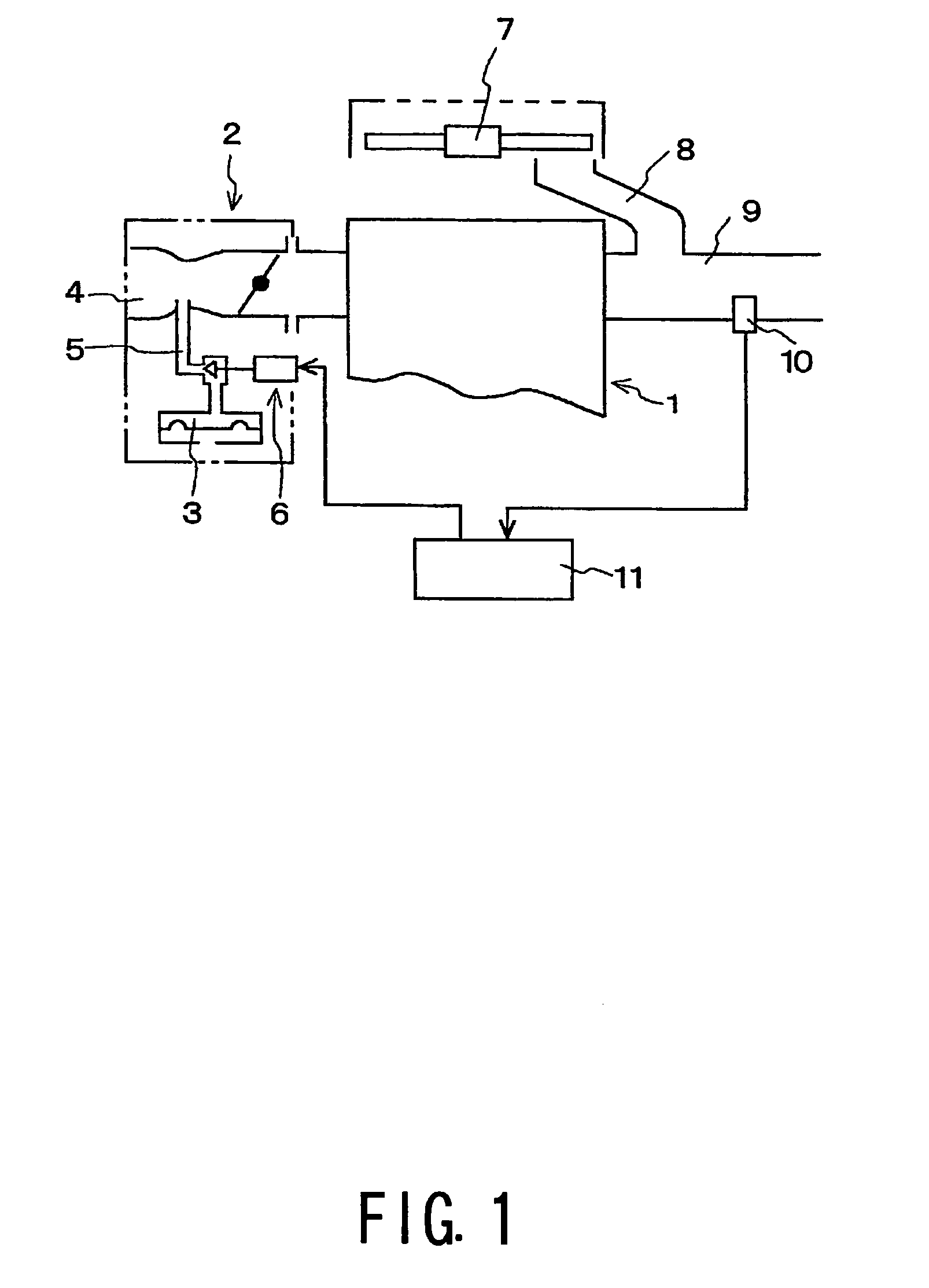
[0019]FIG. 1 depicts a schematic diagram of an embodiment of the present invention in which the apparatus is applied to an engine 1 using a diaphragm-type carburetor corresponding to a carburetor 2 for supplying a fuel. A fuel control member 6, for example, comprising an opening and closing valve is disposed in a fuel passage 5 for delivering the fuel from a fuel metering chamber 3 to a suction passage 4.

[0020] In the present embodiment, engine 1 comprises a forcibly air-cooled engine and is provided with a cooling fan 7. Engine 1 is structured, such that a portion of a discharged air of cooling fan 7 is introduced into an exhaust pipe 9 of engine 1 by an air delivery path 8. Further, a combustion gas sensor 10, e.g., a CO sensor, detecting a concentration of a combustion gas, e.g., a CO gas, component in the exhaust gas is disposed in a downstream side...


PUM


Abstract

An air fuel ratio control apparatus readily satisfies an emission requirement and is particularly preferable for small-displacement engines. The air fuel ratio control apparatus for an engine includes a fuel control member disposed in a fuel passage delivering fuel from a fuel metering chamber of a carburetor supplying the fuel to a suction passage of a comparatively small engine such as a general purpose engine, a working machine engine and the like, a combustion gas sensor disposed in an exhaust pipe in the engine, and an electronic control unit. The control unit actuates the fuel control member in response to a concentration of a combustion gas component in an exhaust gas detected by the combustion gas sensor so as to control a fuel flow rate.

Description

BACKGROUND OF THE INVENTION [0001] 1. Field of the Invention [0002] The present invention relates to air fuel ratio control apparatus, which may be readily applied to satisfy an emission requirement and may be applied to engines or the like, which are used as a power source of a working machine. The apparatus of the present invention is especially suited for use with comparatively compact engines, which have little or no extra space for attaching such apparatus, unlike engines for passenger vehicles, such as a general purpose engine, a compact, general purpose engine; a portable, working machine engine; a lawn mower engine; and the like. [0003] 2. Description of Related Art [0004] In order to reduce a harmful component contained in the exhaust gas of an engine so as to satisfy an emission requirement, air fuel ratio control apparatus has been used, which detects an amount of oxygen contained in the exhaust gas by using an oxygen sensor (hereinafter an “O2 sensor”), controls a fuel f...

Claims


Application Information

Patent Timeline
Patent Type & Authority Applications(United States)
IPC IPC(8): F02D41/04F02D41/14F02D45/00
CPCF02D2400/06F02D41/1453
Inventor NONAKA, TAKUMIIWAANA, MITSUHIRO
Owner ZAMA JAPAN
Why Eureka
Try Eureka