Method for manufacturing a reinforced structural component, and article manufactured thereby

a technology of reinforced structural components and manufacturing methods, applied in the direction of load-supporting pillars, transportation and packaging, other domestic articles, etc., can solve the problems of difficult implementation of prior art approaches and incompatibility of processes with high speed

Inactive Publication Date: 2006-01-26
NOBLE ADVANCED TECH
View PDF12 Cites 33 Cited by
  • Summary
  • Abstract
  • Description
  • Claims
  • Application Information

AI Technical Summary

Benefits of technology

[0006] Disclosed herein is a method for manufacturing a reinforced structural component. In a first step of the method a body of sheet material, such as a body of sheet steel, is subjected to a first forming operation which shapes it into an intermediate structural member. The intermediate structural member defines a channel which extends along at least a portion of its length. In a separate step, a reinforcing insert or other such support member is provided. This support member is disposed in the channel of the intermediate structural member and affixed thereto so that it is retained in said channel. In a subsequent step, a second forming operation is carried out on the intermediate structural member having the support member retained therein. The second forming operation at least partially encloses and fixedly retains the support member within the channel. In particular instances, at least one of the first and second forming operations are a roll-forming operation.

Problems solved by technology

These prior art approaches are difficult to implement since they require that an insert be placed into the interior of a closed beam, or they require that an insert be installed into a two-part beam which process requires subsequent joining of the beam components.
Such processes are not compatible with high speed, and in some instances, continuous, manufacturing processes which are generally favored for the fabrication of such components.

Method used


Image

  • Method for manufacturing a reinforced structural component, and article manufactured thereby
  • Method for manufacturing a reinforced structural component, and article manufactured thereby
  • Method for manufacturing a reinforced structural component, and article manufactured thereby

Examples


Embodiment Construction

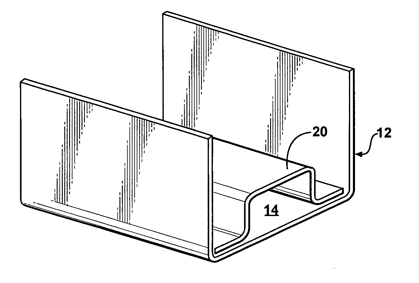
[0019] The present invention is directed to a method for manufacturing a reinforced structural component, such as a pillar, frame or other structural member for a motor vehicle, a building structure, or the like. While the present invention will have utility in the fabrication of metallic and nonmetallic components, it will find particular advantage in fabrication of structural components which include metallic portions. In particular, the present invention is readily adapted for use in high speed metal forming operations such as roll forming.

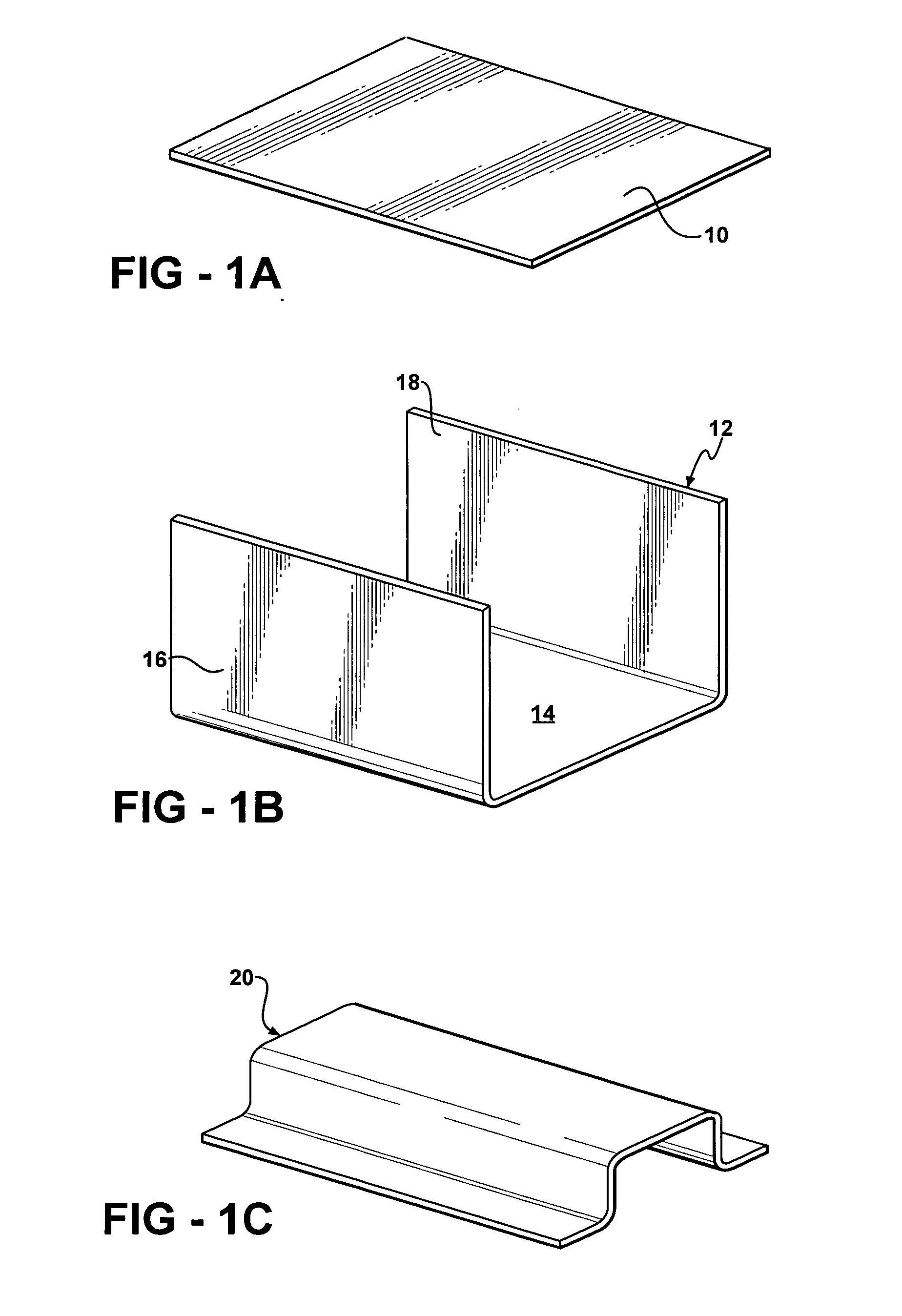
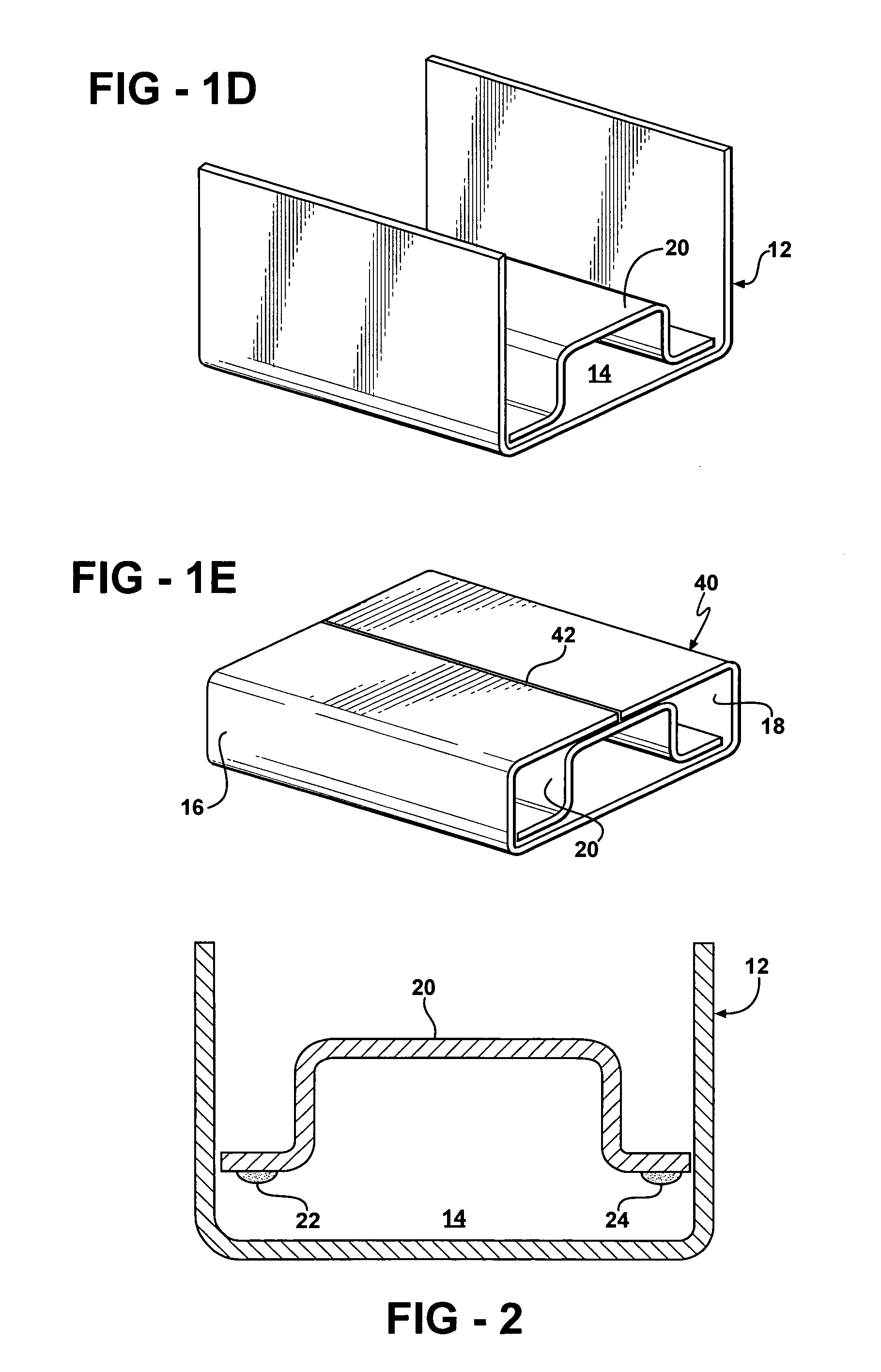
[0020] The present invention will be explained with reference to FIGS. 1A-1E which are schematic depictions of a general process according to the present invention. The process starts, as is shown in FIG. 1A, with a body of a sheet material 10. The sheet material 10 may comprise a ferrous or nonferrous metal, or it may comprise a body of another deformable material such as a polymeric material. As illustrated in FIG. 1, the body of sheet mater...


PUM

PropertyMeasurementUnit
lengthaaaaaaaaaa
mechanical structureaaaaaaaaaa
strengthaaaaaaaaaa

Abstract

A reinforced structural component is manufactured by forming an intermediate structural member which defines a channel extending along at least a portion of its length. A support member is disposed in the channel and affixed to the intermediate structural member. A second forming operation is carried out on the combination of the intermediate structural member and support member so as to partially enclose and fixedly retain the support member therein. The method may be applied to metallic and nonmetallic structures, and may be utilized in conjunction with high speed metal forming processes such as roll forming. Disclosed herein are structures made according to the method as well as use of the method in the manufacture of structural components for motor vehicles.

Description

RELATED APPLICATIONS [0001] This application claims priority of U.S. Provisional Patent Application Ser. No. 60 / 586,009 filed Jul. 7, 2004, entitled “Method of Inserting Structural Support Member in Roll-Formed Part” and U.S. Provisional Patent Application Ser. No. 60 / 588,118 filed Jul. 14, 2004, entitled “Reinforcement for a B-Pillar of an Automotive Vehicle.”FIELD OF THE INVENTION [0002] This invention relates generally to the manufacture of reinforced structural components such as frame members for motor vehicles. More specifically, the invention relates to a method for incorporating a support member in such a component. In particular, the invention relates to a process for incorporating a reinforcing support member in a roll-formed component. BACKGROUND OF THE INVENTION [0003] The structural integrity of the passenger and cargo compartments of a motor vehicle relies upon the use of support pillars and other frame members. These structural components require a combination of high...

Claims


Application Information

Patent Timeline
Patent Type & Authority Applications(United States)
IPC IPC(8): B21D47/00
CPCB21D47/04B21D53/88Y10T29/49627Y10T29/49625Y10T29/49634Y10T29/49622
Inventor BLADOW, JEFFREYJAEGER, WALTERFILIPEK, GREGMURRAY, MAJOR DANIELBAKER, RONKANCHERLA, GOPI KALYAN CHAKRAVARTHYTAANK, HIMAT
Owner NOBLE ADVANCED TECH
Why Eureka
Try Eureka