Control device of internal combustion engine

a control device and internal combustion engine technology, applied in the direction of electric control, machines/engines, mechanical equipment, etc., can solve the problems of unburned components, inability to completely prevent the foregoing fuel adhesion, and inability to achieve the effect of lowering the performance of the internal combustion engin

Inactive Publication Date: 2006-01-26
TOYOTA JIDOSHA KK
View PDF4 Cites 101 Cited by
  • Summary
  • Abstract
  • Description
  • Claims
  • Application Information

AI Technical Summary

Benefits of technology

[0014] The invention has been made for overcoming the above problems, and an object of the invention is to provide a control device of an internal combustion engine configured to share fuel injection between a first fuel injection mechanism injecting fuel into a cylinder and a second fuel injection mechanism injecting the fuel into an intake manifold, and particularly to provide a control device, which can suppress dilution of a lubricating oil without lowering a performance of the internal combustion engine even when the fuel injected from the first fuel injection mechanism may dilute the lubricating oil of the internal combustion engine.

Problems solved by technology

However, the in-cylinder injector may cause the following disadvantage during a cold state of the engine because it directly injects the fuel into the cylinder.
However, even this intake stroke injection cannot completely prevent the foregoing fuel adhesion, and a part of the fuel will remain in the adhering state within the cylinder after the combustion without being burned.
This causes occurrence of black smoke, increase in unburned components and others, and thus impairs the emission characteristics.
If the fuel frequently dilutes the lubricating oil, a rate of the mixed fuel with respect to the whole lubricating oil gradually increases, and this will cause adverse effects on the lubricating performance of the internal combustion engine such as lowering of the lubricating performance.
Conversely, when the degree of fuel-dilution of the whole lubricating oil increases to such an extent that further fuel-dilution will cause unignorable adverse effects such as lowering of the lubrication performance, the fuel injection is controlled to suppress the dilution of the lubricating oil with the fuel.
However, if the fuel injection manner or form (specifically, a fuel injection time of the in-cylinder injector and a fuel pressure) is changed as disclosed in Japanese Patent Laying-Open No. 2003-322044, it may become impossible to achieve a performance of the internal combustion engine, which is basically required in connection with an engine speed, a load factor and others.

Method used


Image

  • Control device of internal combustion engine
  • Control device of internal combustion engine
  • Control device of internal combustion engine

Examples


Embodiment Construction

[0032] An embodiment of the invention will now be described with reference to the drawings. In the following description, the same portions bear the same reference numbers and the same names, and achieve the same functions. Therefore, description thereof is not repeated.

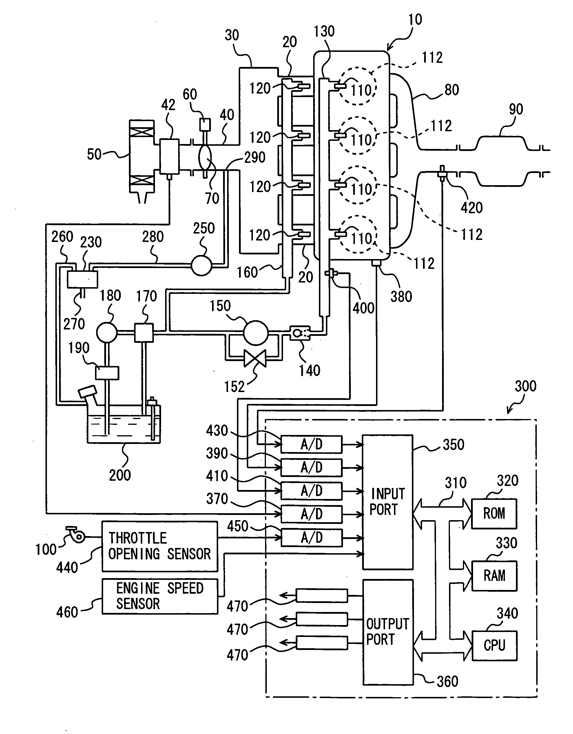
[0033]FIG. 1 shows a schematic structure of an engine system controlled by an engine ECU (Electronic Control Unit), which is a control device of an internal combustion engine according to an embodiment of the invention. Although FIG. 1 shows an inline four-cylinder gasoline engine, the invention is not restricted to such an engine.

[0034] As shown in FIG. 1, an engine 10 includes four cylinders 112, which are each connected to a common surge tank 30 via a corresponding intake manifold 20. Surge tank 30 is connected to an air cleaner 50 via an intake duct 40. An air flow meter 42 as well as a throttle valve 70 driven by an electric motor 60 are arranged in intake duct 40. The degree of opening of throttle valve 70 is...


PUM


Abstract

An engine ECU executes a program including a step of lowering a pressure of fuel supplied to an in-cylinder injector when it is determined that a degree of dilution of an oil with the fuel is large, a step of calculating a fuel injection period TAUd of the in-cylinder injector with a low fuel pressure, a step of calculating a fuel pressure Pr(0) of the in-cylinder injector required according to an engine speed and a load, a step of calculating a fuel injection period TAUd(0) of the in-cylinder injector with Pr(0), and a step of substituting TAUd(0) for TAUd when TAUd is equal to or larger than TAUd(0).

Description

[0001] This nonprovisional application is based on Japanese Patent Application No. 2004-214396 filed with the Japan Patent Office on Jul. 22, 2004, the entire contents of which are hereby incorporated by reference. BACKGROUND OF THE INVENTION [0002] 1. Field of the Invention [0003] The present invention relates to a control device of an internal combustion engine including a first fuel injection mechanism (i.e., in-cylinder injector) for injecting fuel into a cylinder and a second fuel injection mechanism (i.e., intake manifold injector) for injecting fuel into an intake manifold or an intake port, and particularly to a technique suppressing dilution of a lubricating oil of the internal combustion engine with fuel injected from the first fuel injection mechanism. [0004] 2. Description of the Background Art [0005] A certain kind of known internal combustion engine includes an intake manifold injector for injecting fuel into an intake manifold of an engine and an in-cylinder injector ...

Claims


Application Information

Patent Timeline
Patent Type & Authority Applications(United States)
IPC IPC(8): F02B7/00F02D41/04F02D41/22F02D41/38F02D41/40
CPCF02B23/104Y02T10/123F02D41/047F02D41/22F02D41/3094F02D41/3836F02D41/3845F02D41/3854F02D41/40F02D2041/3881F02D2041/389F02D2200/0602F02D2250/11F02D2250/31F02M63/0225F02M63/029F02M69/044F02M69/046Y02T10/44F02B2075/125Y02T10/12Y02T10/40
Inventor MASHIKI, ZENICHIRO
Owner TOYOTA JIDOSHA KK
Why Eureka
Try Eureka