
Methods and systems for cementing wells that lack surface casing

a technology of cementing wells and casings, applied in the field of cementing casings, can solve the problems of increasing the risk of well bore cave-in, additional challenges in cementing operations,

Active Publication Date: 2006-01-26
HALLIBURTON ENERGY SERVICES INC
View PDF98 Cites 49 Cited by
  • Summary
  • Abstract
  • Description
  • Claims
  • Application Information

AI Technical Summary

Benefits of technology

[0010] According to still another aspect of the invention, there is provided a method for cementing a casing in an open well bore having no surface casing, wherein an annulus is defined between the casing and the well bore, the method having: injecting a cement composition into the annulus at a level below the mouth of the well bore a sufficient distance to prevent the cement position from flowing out the top of the annulus, whereby the weight of the cement composition in the annulus initiates fluid flow in the well bore in a reverse circulation direction before the cement composition flows out the top of the annulus; and taking circulation fluid returns from the inner diameter of the casing.
[0015] According to yet another aspect of the invention, there is provided a system for cementing a casing in an open well bore having no surface casing, wherein an annulus is defined between the casing and the well bore, the system having: a cement composition pump; a cement composition injector fluidly connected to the cement composition pump, wherein the injector is positioned at a level below the mouth of the well bore a sufficient distance to prevent the cement composition from flowing out the top of the annulus, whereby the weight of the cement composition in the annulus initiates fluid flow in the well bore in a reverse circulation direction before the cement composition flows out the top of the annulus; and a coupler attached to an exposed end of the casing for taking circulation fluid returns from the inner diameter of the casing.

Problems solved by technology

Well configurations as illustrated in FIG. 1 present additional challenges for conducting cementing operations.
For example, cementing of these wells is problematic because there is no well head forming a seal of the annulus, there is no well head providing nipple connections for fluid communication with the inner diameter of the casing or the annulus, and there is increased risk of well bore cave-in.

Method used


Image

  • Methods and systems for cementing wells that lack surface casing
  • Methods and systems for cementing wells that lack surface casing
  • Methods and systems for cementing wells that lack surface casing

Examples


Embodiment Construction

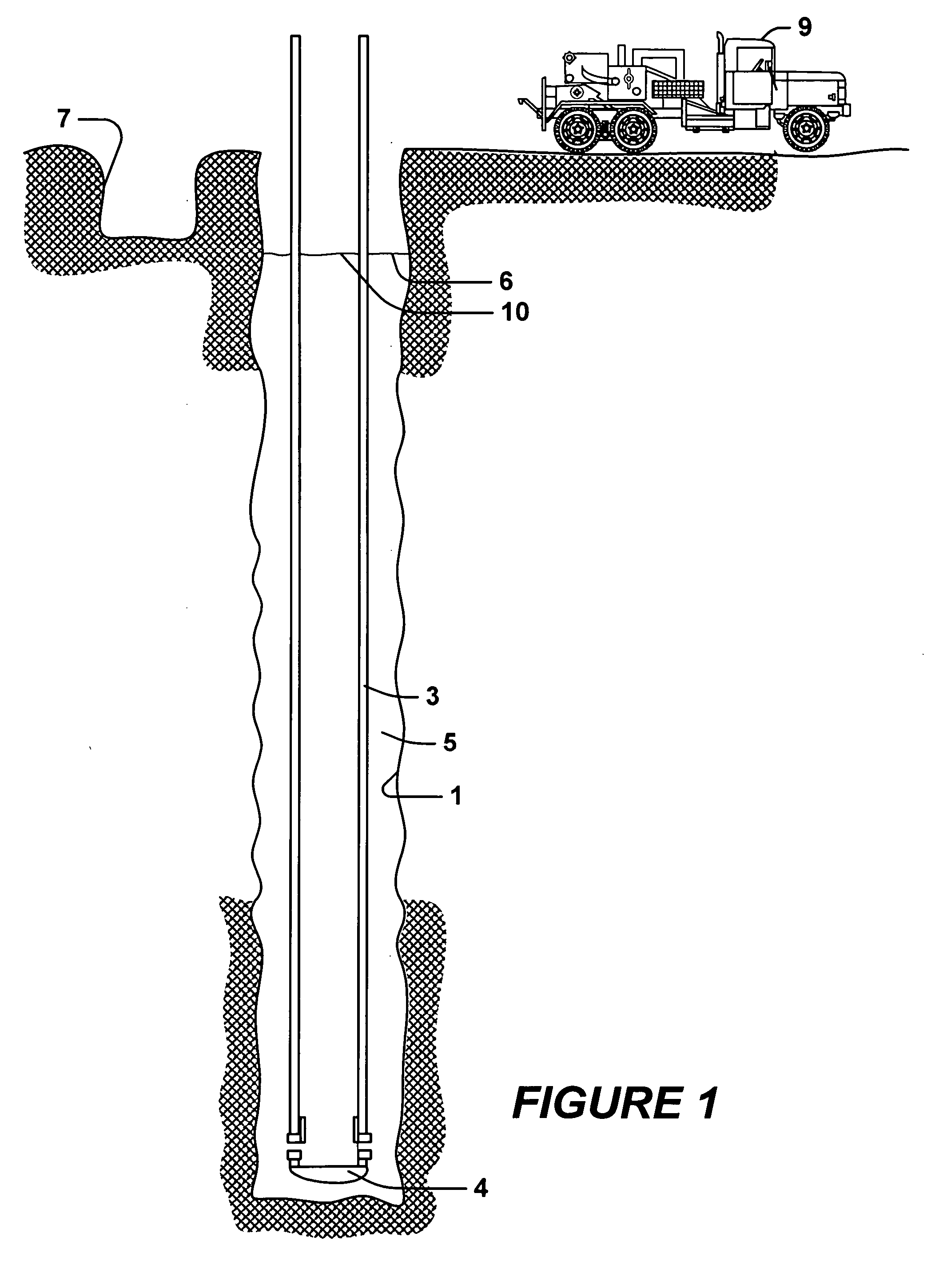
[0039] This invention relates to cementing casing in well bores drilled in subterranean formations. In particular, this invention relates to methods for cementing casing in a well bore without surface casing or a well head.

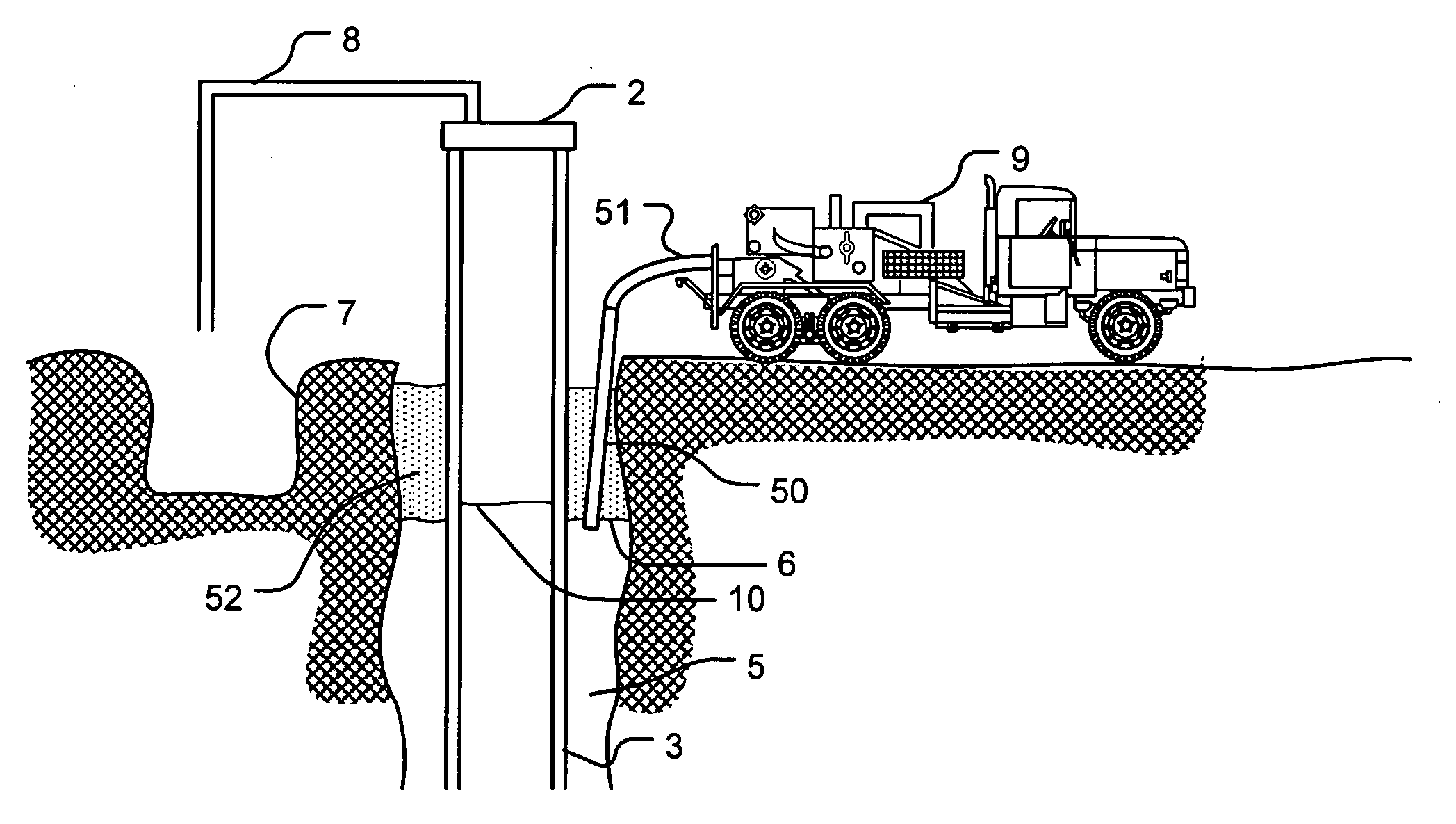
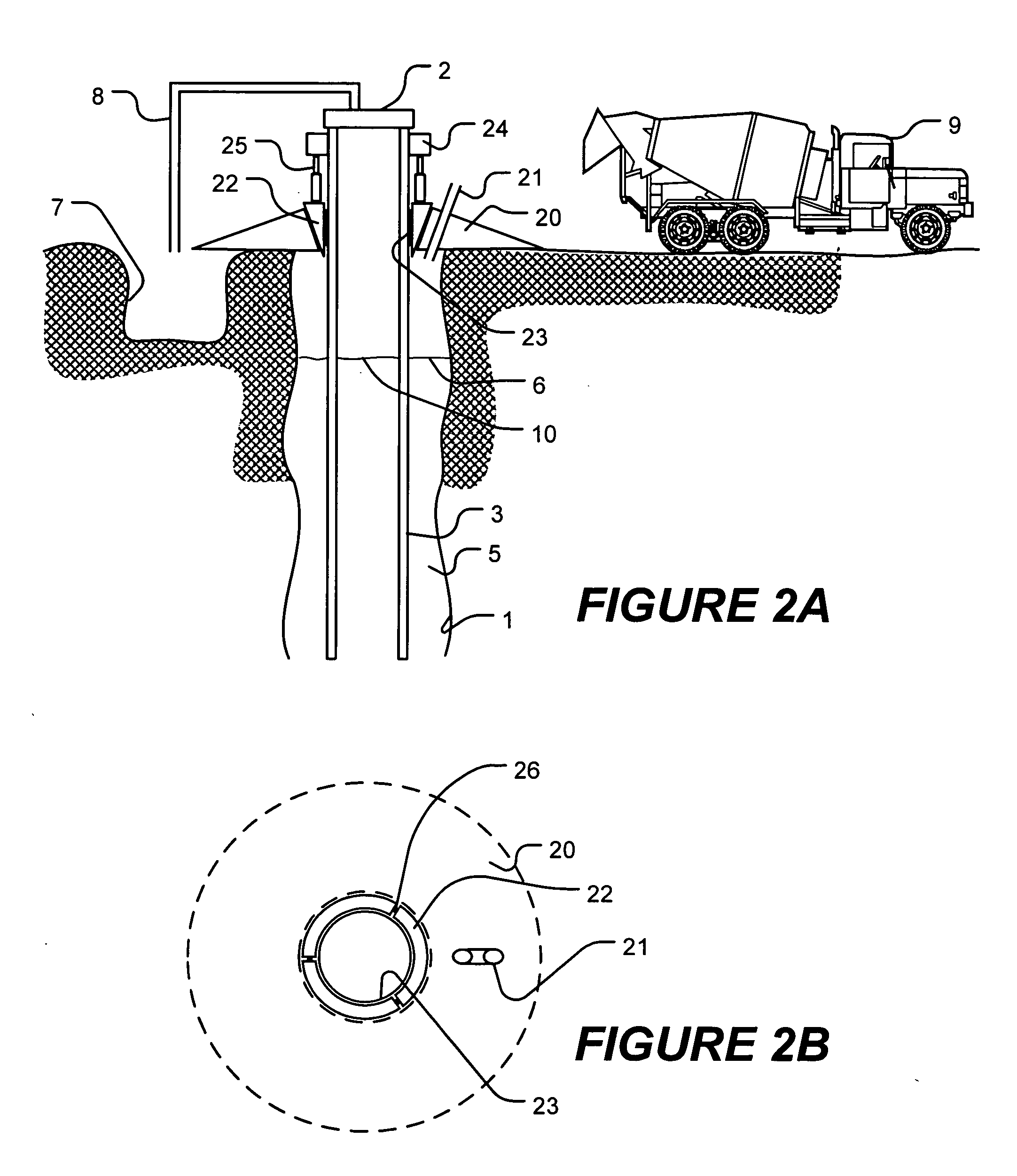
[0040]FIG. 2A illustrates a cross-sectional, side view of a well bore and casing. Similar to the well bore illustrated in FIG. 1, this well bore has a casing 3 sticking out of the mouth of the well bore 1 without an installed surface casing or well head. An annulus 5 is defined between the casing 3 and the well bore 1. A truck 9 is parked near the well bore and a reservoir is also located nearby. The well bore 1 is also filed with circulation fluid such that an annulus circulation fluid surface 6 is approximately level with an ID circulation fluid surface.

[0041] An annular plug 20 is positioned over the exposed end of the casing 3 and lowered until it rests on the soil at the mouth of the well bore 1. As illustrated, the annular plug is a conical structure with ...


PUM


Abstract

A method for cementing a casing in an open well bore having no surface casing, wherein an annulus is defined between the casing and the well bore, the method having: sealing the annulus at the mouth of the well bore with a seal; pumping a cement composition into the annulus through the seal; and taking circulation fluid returns from the inner diameter of the casing. A system for cementing a casing in an open well bore having no surface casing, wherein an annulus is defined between the casing and the well bore, the system having: a seal of the annulus at the mouth of the well bore; a cement composition pump fluidly connected to the annulus through the seal; and a coupling connected to the exposed end of the casing for taking circulation fluid returns from the inner diameter of the casing. A seal of a well bore annulus at the mouth of an open well bore having a casing extending there from and no surface casing, the seal having: an annular plug around the casing in the annulus below and proximate the mouth of the well bore, wherein the annular plug has conduit through the annular plug allowing fluid communication with the annulus below the annular plug; an anchor attachable to the casing above the annular plug; and at least one jack positioned between the annular plug and the anchor, wherein the at least one jack pushes the annular plug downwardly away from the anchor.

Description

BACKGROUND OF THE INVENTION [0001] This invention relates to cementing casing in well bores drilled in subterranean formations. In particular, this invention relates to methods for cementing casing in a well bore without surface casing or a well head. [0002] Typically, prior to cement operations, a relatively larger diameter surface casing is run into the well bore to a relatively shallow depth. A casing string is then inserted in a well bore. Circulation fluid fills the inner diameter (“ID”) of the casing and the caseing-by-well bore annulus. For purposes of this disclosure, “circulation fluid” is defined as circulation fluid, drilling mud, formation fluids and / or any other fluid typically found in pre-cemented wells. Once the casing is run into the well bore, it is desirable to flow a cement composition into the annulus and allow the cement composition to harden to completely seal the annulus and secure the casing in the bore hole. [0003] However, in some well bores, no surface ca...

Claims


Application Information

Patent Timeline
IPC IPC(8): E21B33/13E21B33/02E21B33/14
CPCE21B33/02E21B33/14E21B33/05E21B33/04
Inventor BADALAMENTI, ANTHONY M.TURTON, SIMONBLANCHARD, KARL W.FAUL, RONALD R.CROWDER, MICHAEL G.ROGERS, HENRY E.GRIFFITH, JAMES E.
Owner HALLIBURTON ENERGY SERVICES INC
Features
  • Generate Ideas
  • Intellectual Property
  • Life Sciences
  • Materials
  • Tech Scout
  • Unparalleled Data Quality
  • Higher Quality Content
  • 60% Fewer Hallucinations
Learn More