
Communication terminal

Inactive Publication Date: 2006-01-26
PANASONIC CORP
View PDF8 Cites 3 Cited by
  • Summary
  • Abstract
  • Description
  • Claims
  • Application Information

AI Technical Summary

Benefits of technology

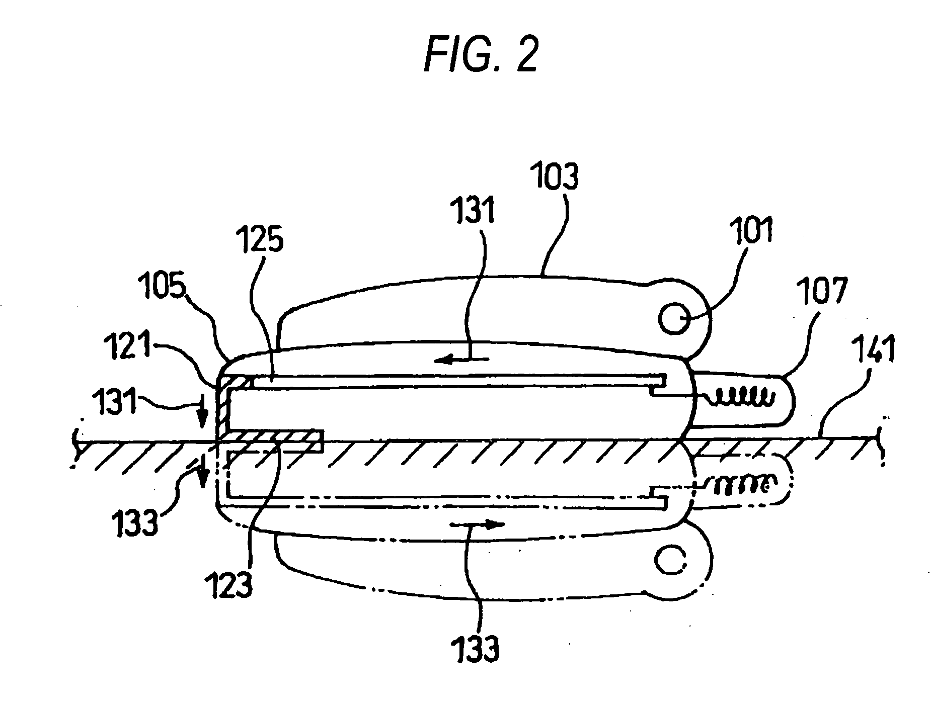
[0008] A high-frequency current flows from the antenna to the board. Since a high-frequency current of an opposite phase flows through a metal plate because of the mirror image effect in a state in which the communication terminal is placed on the metal plate with the rear of the casing down, the high-frequency current flowing through the board of the communication terminal is canceled and thus the radiation of the antenna is weakened. In the state, the first conductor part is electrically connected to the metal plate or is short-circuited in a high-frequency manner to the metal plate and the second conductor part is connected to the GND of the board; the components perpendicular to the metal plate strengthen each other by the mirror image effect and thus the high-frequency current flowing through the top of the board flows into the second conductor part as an extension of the board, producing an electric field perpendicular to the metal plate. Thus, the antenna gain is not degraded and the reception sensitivity can be kept good. The first conductor part and the second conductor part can be installed with almost no need for changing the size or the design of the communication terminal.
[0012] A high-frequency current flows from the antenna to the board. Since a high-frequency current of an opposite phase flows through a metal plate because of the mirror image effect in a state in which the communication terminal is placed on the metal plate with the rear of the casing down, the high-frequency current flowing through the board of the communication terminal is canceled and thus the radiation of the antenna is weakened. In the state, the first conductor part is electrically connected to the metal plate or is short-circuited in a high-frequency manner to the metal plate and the second conductor part is connected to the shield case attached to the board; the components perpendicular to the metal plate strengthen each other by the mirror image effect and thus the high-frequency current flowing through the top of the board flows into the second conductor part as an extension of the board, producing an electric field perpendicular to the metal plate. Thus, the antenna gain is not degraded and the reception sensitivity can be kept good. If the length of the board cannot be taken to the vicinity of the bottom face of the casing because of the positional relationship with other parts, the first conductor part and the second conductor part can be formed. The first conductor part and the second conductor part can be installed with almost no need for changing the size or the design of the communication terminal.

Problems solved by technology

Thus, the matching state comes undone and the antenna gain is degraded; this is a problem.
However, in the technique of installing the rib at the rear of the small radio described above, the thickness of the main body increases as much as the rib thickness and thus the small radio cannot be slimmed and the rib gives a large impact from the aspect of the design and thus the outward shape is impaired; this is a problem.
In the technique switching of an antenna element and a matching circuit by a switching element or the technique of providing a subantenna, the circuit configuration and control become complicated and the cost increases and in addition, the technique is also undesirable for miniaturization.

Method used


Image

  • Communication terminal
  • Communication terminal
  • Communication terminal

Examples


first embodiment

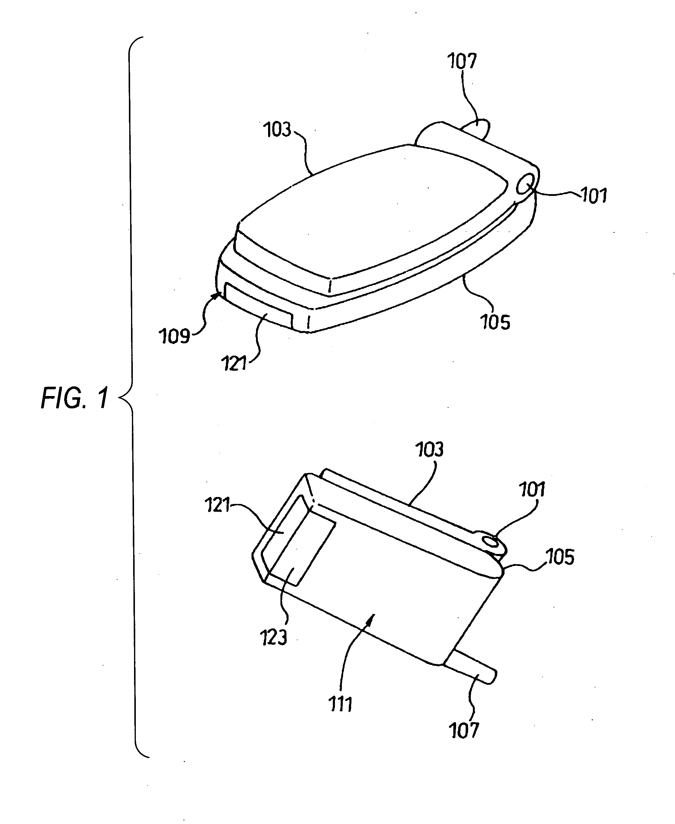
[0027]FIG. 1 is an external view to show a communication terminal of a first embodiment. As shown in the figure, the communication terminal of the embodiment has two foldable casings (upper casing 103 and lower casing 105) joined by a hinge 101 and an antenna 107 installed on the lower casing 105. A bottom surface of the lower casing 105 denoted by numeral 109 in FIG. 1 and a rear denoted by numeral 111 are formed roughly at the right angle. A radiating element 121 corresponding to a second conductor part in claims is provided so that it is exposed flush with the bottom surface 109 of the lower casing 105, and an auxiliary bottom board 123 corresponding to a first conductor part is provided so that it is exposed flush with the rear 111 of the lower casing 105; the radiating element and the auxiliary bottom board are joined roughly at the right angle. The radiating element 121 and the auxiliary bottom board 123 are conductors.

[0028] The main part of the communication terminal of the...

second embodiment

[0036]FIG. 5 is a schematic representation to schematically show the main part of a communication terminal of a second embodiment from a bottom face. FIG. 6 is a schematic representation to schematically show the communication terminal of the second embodiment from a side (a) and from a rear (b). Parts identical with those in FIGS. 1 and 2 (first embodiment) are denoted by the same reference numerals in FIGS. 5 and 6.

[0037] The communication terminal of the second embodiment is provided with a board 125, metal fittings 201, a radiating element 203, and an auxiliary bottom board 205 inside a lower casing 105, as shown in FIGS. 5 and 6. The radiating element 203 and the auxiliary bottom board 205 are formed in one piece. The metal fittings 201 are fittings for fixing parts 207 of a connector, a jack, etc., to the board 125 and are electrically connected to GND of the board 125. Further, the radiating element 203 is provided with roof-type spring parts 209 to come in contact with the ...

third embodiment

[0041]FIG. 7 is an external view to show a state in which a rear cover of a lower casing of a communication terminal of a third embodiment is removed from the rear. FIG. 8 is a schematic representation to schematically show the main part of the communication terminal of the third embodiment from a side. Parts identical with those in FIGS. 1 and 2 (first embodiment) are denoted by the same reference numerals in FIGS. 7 and 8.

[0042] The communication terminal of the third embodiment is provided with a board 301, a shield case 303 attached to the rear of the board 301, a radiating element 305, and an auxiliary bottom board 307 inside a lower casing 105, as shown in FIGS. 7 and 8. The radiating element 305 and the auxiliary bottom board 307 are formed in one piece on the rear of the lower casing 105 of the board 301. The radiating element 305 is formed in such a manner that a part of the auxiliary bottom board 307 is lifted up from the rear and is pressed against the shield case 303. T...


PUM


Abstract

An object of the invention is to provide a communication terminal capable of keeping the reception sensitivity good if the communication terminal is placed on a metal plate with the communication terminal laid on its side without the need for changing the size or the design of the main body of the communication terminal. A board (125) to which an antenna (107) is connected is provided inside a lower casing (105). The board (125) is provided with a GND plane to which a radiating element (121) is connected. An auxiliary bottom board (123) is joined to the radiating element (121) in a roughly perpendicular direction thereto. The radiating element (121) and the auxiliary bottom board (123) are conductors. A high-frequency current (131) flows into the board (125). Since a high-frequency current (133) of an opposite phase flows through a metal plate (141) because of the mirror image effect in a state in which the communication terminal is placed on the metal plate (141), the high-frequency current (131) is canceled and the radiation of the antenna (107) is weakened. However, the components perpendicular to the metal plate (141) do not cancel each other because of the mirror image effect and thus the radiating element (121) forms a dipole antenna symmetrically with the metal plate (141).

Description

Technical Field [0001] This invention relates to a communication terminal and in particular to a communication terminal capable of keeping the reception sensitivity good if the communication terminal is placed on a metal plate of a steel desk, etc., in a state in which the communication terminal is laid on its side. BACKGROUND ART [0002] Usually, a communication terminal such as a mobile telephone or a PHS is provided with an antenna. If the communication terminal is placed on a metal plate of a steel desk, etc., with the communication terminal laid on its side, the antenna is brought close to the metal plate and thus interconnection occurs and a current of an opposite phase to the current flowing through the antenna flows into the metal face, changing the radiation directivity of the antenna and largely changing the impedance characteristic. Thus, the matching state comes undone and the antenna gain is degraded; this is a problem. [0003] To solve this problem, a small radio describ...

Claims


Application Information

Patent Timeline
IPC IPC(8): H01L29/00H01Q1/24H01Q1/48H01Q9/30H01Q19/00H04B1/38H04B1/3822H04M1/02H04M1/21H04M1/725
CPCH01Q1/242H01Q1/243H04M1/0214H01Q9/30H01Q19/00H01Q1/48H01Q1/24
Inventor TANAKA, NOBUAKISATO, KENJISAITO, EIJI
Owner PANASONIC CORP
Learn More