Image projecting device and method

a projecting device and image technology, applied in the field of compact image projecting devices and methods, can solve the problems of low brightness, low energy efficiency, non-uniform output image, etc., and achieve the effects of reducing the associated effects of speckles, high efficiency, and facilitating image projection

Inactive Publication Date: 2006-01-26
EXPLAY
View PDF13 Cites 149 Cited by
  • Summary
  • Abstract
  • Description
  • Claims
  • Application Information

AI Technical Summary

Benefits of technology

[0016] There is a need in the art to facilitate the projection of images by providing a novel miniature projector device and method. The device of the present invention is lightweight and highly efficient, and is capable of utilizing a high-ratio polarized light source, high-efficiency SLM performing digital processing of data to be imaged so as to significantly reduce the speckles' associated effects, as well as performing digital processing of a projected image to improve its uniformity.
[0022] (iv) the light source system comprises a multi-mode laser, thereby reducing a speckle effect in an integrated speckle pattern produced by the multiple modes, as compared to that of a single mode;
[0030] Preferably, the device of the present invention comprises an image processor system (control unit) operable to carry out at least one of the following: applying digital processing to data indicative of an image to be projected so as to avoid or at least significantly reduce the speckle-associated effects in the projected image; processing data indicative of the projected image to correct for non-uniformities in the light intensity; and analyzing data indicative of the environmental condition to adjust the intensity and / or the color mixture of the incident light beam.
[0034] The device of the present invention can be used with any conventional video generating device to project images onto an external screen surface. The device can be operable in a specific system to project the same image with two different angles of projection, thereby enabling observation of the same image by two different observers, and also allows for private operation of the respective one of the images by each of the observers through his viewing area.
[0035] The technique of the present invention allows for combining images projected by several micro-projectors of the present invention, thereby allowing the creation of a large combined image; projecting the image onto a concaved screen surface; and the creation of stereoscopic images by using two micro-projectors or the single micro-projector equipped with a rotating mirror.
[0044] (d) a speckle effect in a projected image is reduced by using a multi-mode laser for the creation of said at least one incident light beam.

Problems solved by technology

Common optical difficulties in the design of known projectors based on a microdisplay are as follows: low energy efficiency; low brightness and non-uniformity of the output image due to the source non-uniform intensity distribution (i.e. Gaussian distribution over the SLM surface) and intensity losses; low focus depth of the output image.
In laser based projectors, the “speckle” phenomena of a Laser source according to which a granular pattern of light pervades the image, is also considered as a technical difficulty.
Other common difficulties directly related to the optical difficulties and to the hardware implementation are: size, weight, optical complexity, power consumption and the mobility of the overall projecting device.

Method used


Image

  • Image projecting device and method
  • Image projecting device and method
  • Image projecting device and method

Examples


Embodiment Construction

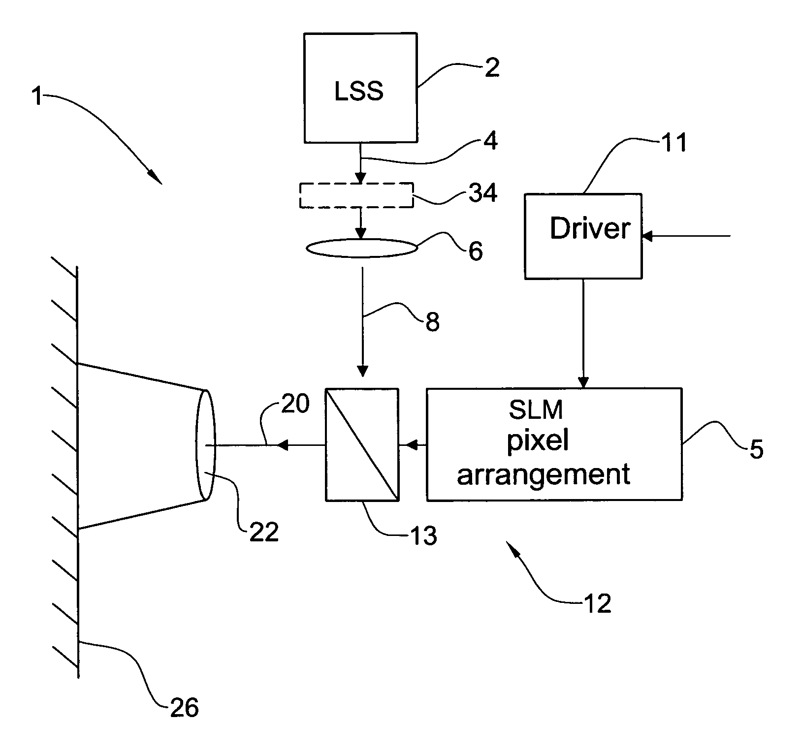
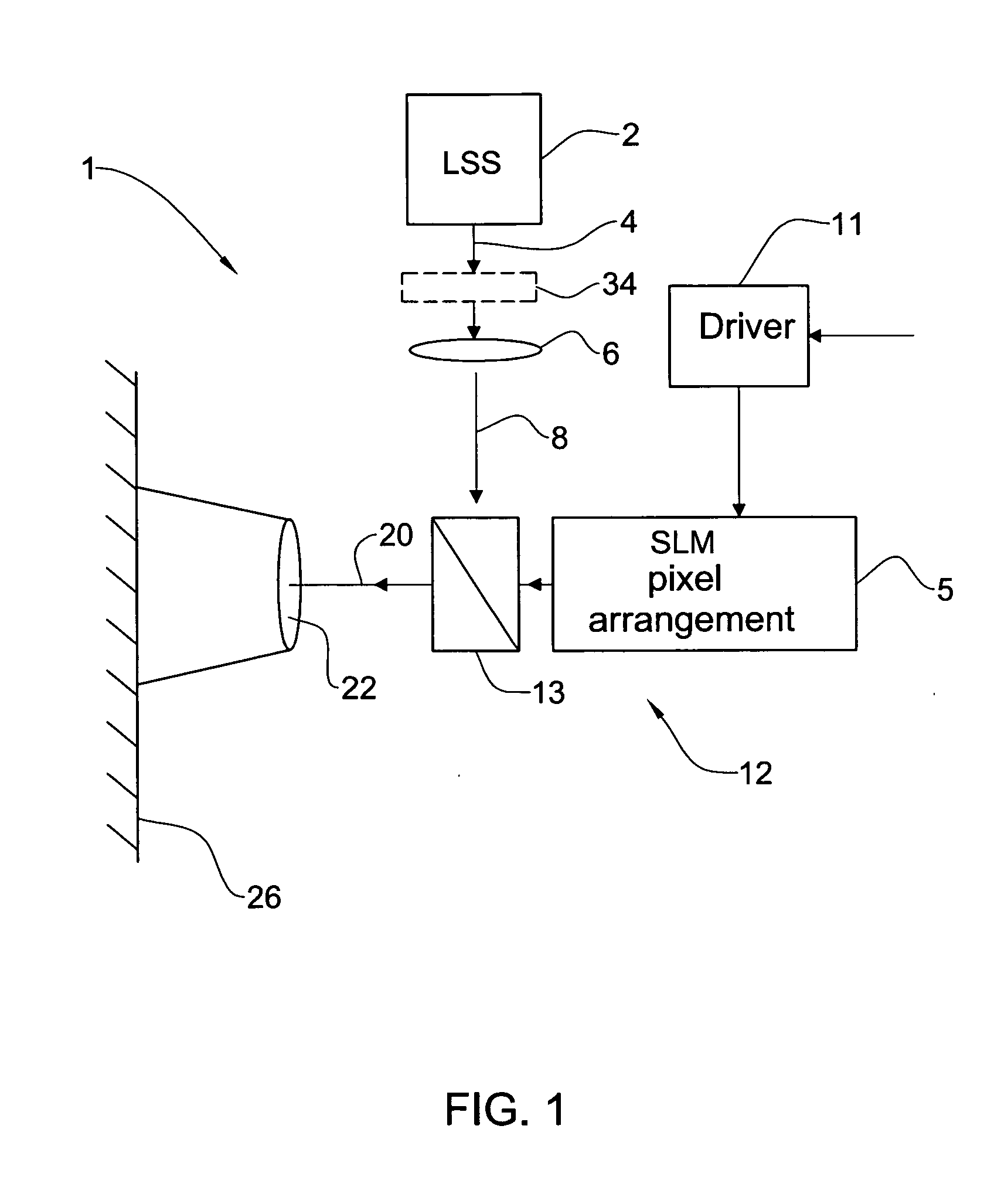
[0058] Referring to FIG. 1 there is schematically illustrated a block diagram of a projecting device 1 according to the invention showing the optical components of a light propagation scheme. The device 1 comprises a light source system LSS including a light source 2 generating a collimated light beam 4; an SLM unit 12; an image projection optics 22 (e.g., a magnifying lens arrangement) located in the optical path of light emerging from the SLM unit and propagating towards a projecting (or screen) surface 26.

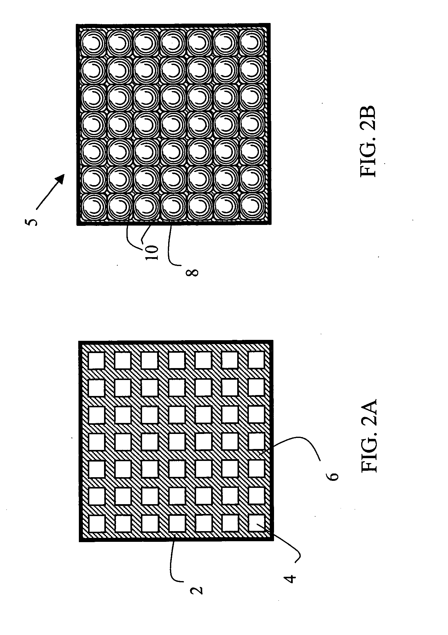
[0059] The SLM unit 12 (which in the present example is of reflective type) includes a pixel arrangement 5 formed by a pixel assembly (the so-called “windowed structure”) and a lenslet assembly (as will be described more specifically further below) enclosed between two substrates (e.g., glass substrates), and includes a beam splitter / combiner 13 (preferably polarization beam splitter). Preferably, the device 1 includes a diffractive element 34 (“top-hat beam shaping optical ele...


PUM


Abstract

An image projecting device and method are presented. The device comprises a light source system, a spatial light modulator (SLM) unit, and an image projection optics accommodated at the output side of the SLM unit. The SLM unit may be reflective or transmissive. The SLM unit comprises an SLM pixel arrangement enclosed between two glass substrates. The pixel array arrangement is formed by a pixel array assembly and at least one microlens assembly. The microlens assembly includes at least one microlens array accommodated proximate of the pixel array assembly. The light source system may comprise n light sources and a light converting means in optical path of light generated by the n light sources, to thereby produce m light beams of different wavelength ranges, wherein m>n. The light source system may comprise a multi-mode laser, thereby reducing a speckle effect in an integrated speckle pattern produced by the multiple modes, as compared to that of a single mode.

Description

CROSS REFERENCE TO RELATED APPLICATIONS [0001] The present application is a continuation-in-part of International Application No. PCT / IL2003 / 000025, filed Jan. 8, 2003. The entire contents of this application being hereby incorporated herein by reference.FIELD OF THE INVENTION [0002] This invention relates to a compact-size image projecting device and method. BACKGROUND OF THE INVENTION [0003] Microdisplays are miniaturized displays, typically with a screen size of less than 1.5″ in diagonal. Microdisplays are commonly used in data projectors, head mounted displays, and in the traditional viewfinders of digital cameras. They can be implemented within compact projectors, in viewfinders of handheld Internet appliances and in mobile phones for Web surfing and videoconferences, as full computer screens can be viewed in these devices. [0004] Most microdisplays use a light-valve made of a silicon chip as the substrate material. The chip also houses the addressing electronics (at least an ...

Claims


Application Information

Patent Timeline
Patent Type & Authority Applications(United States)
IPC IPC(8): G02B27/10H04N9/31
CPCH04N9/3129H04N9/3197H04N9/315
Inventor SHARON, IIANZALEVSKY, ZEEVMANOR, GOLANKAPELLNER, YUVAL
Owner EXPLAY
Why Eureka
Try Eureka