Heat exchange system for a cavitation chamber

a cavitation chamber and heat exchange technology, applied in the field of sonoluminescence, can solve the problems of limited control of the conditions applied to the liquid, many aspects of the phenomena have not yet been characterized, etc., and achieve the effect of promoting specific reactions in the cavitation chamber and lowering the temperature of the cavitation medium

Inactive Publication Date: 2006-01-26
IMPULSE DEVICES INC
View PDF12 Cites 28 Cited by
  • Summary
  • Abstract
  • Description
  • Claims
  • Application Information

AI Technical Summary

Problems solved by technology

Although it is generally recognized that during the collapse of a cavitating bubble extremely high temperature plasmas are developed, leading to the observed sonoluminescence effect, many aspects of the phenomena have not yet been characterized.
Although a variety of sonoluminescence systems have been designed, typically these systems allow limited control of the conditions applied to the liquid within the chamber.

Method used


Image

  • Heat exchange system for a cavitation chamber
  • Heat exchange system for a cavitation chamber
  • Heat exchange system for a cavitation chamber

Examples


Embodiment Construction

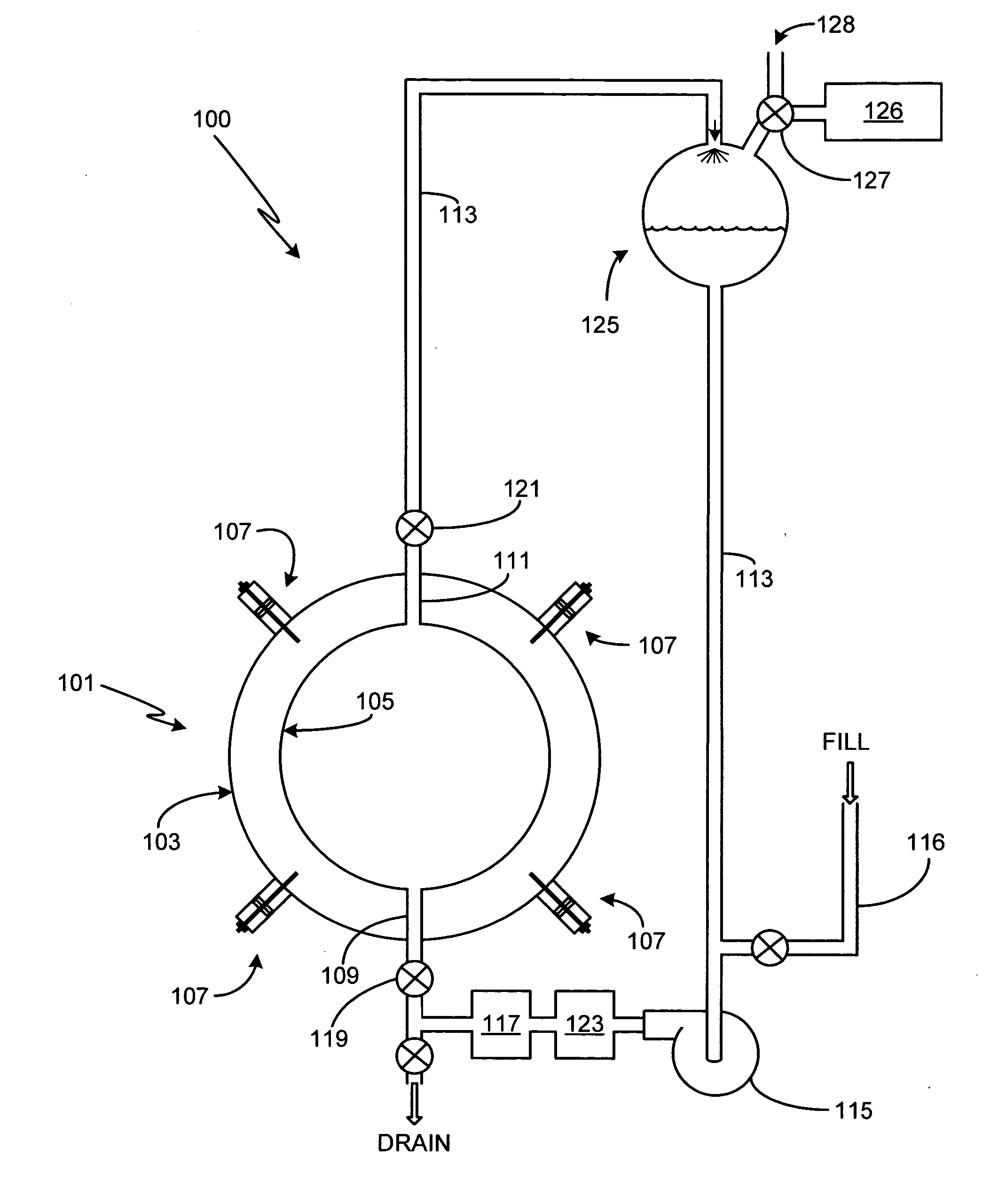
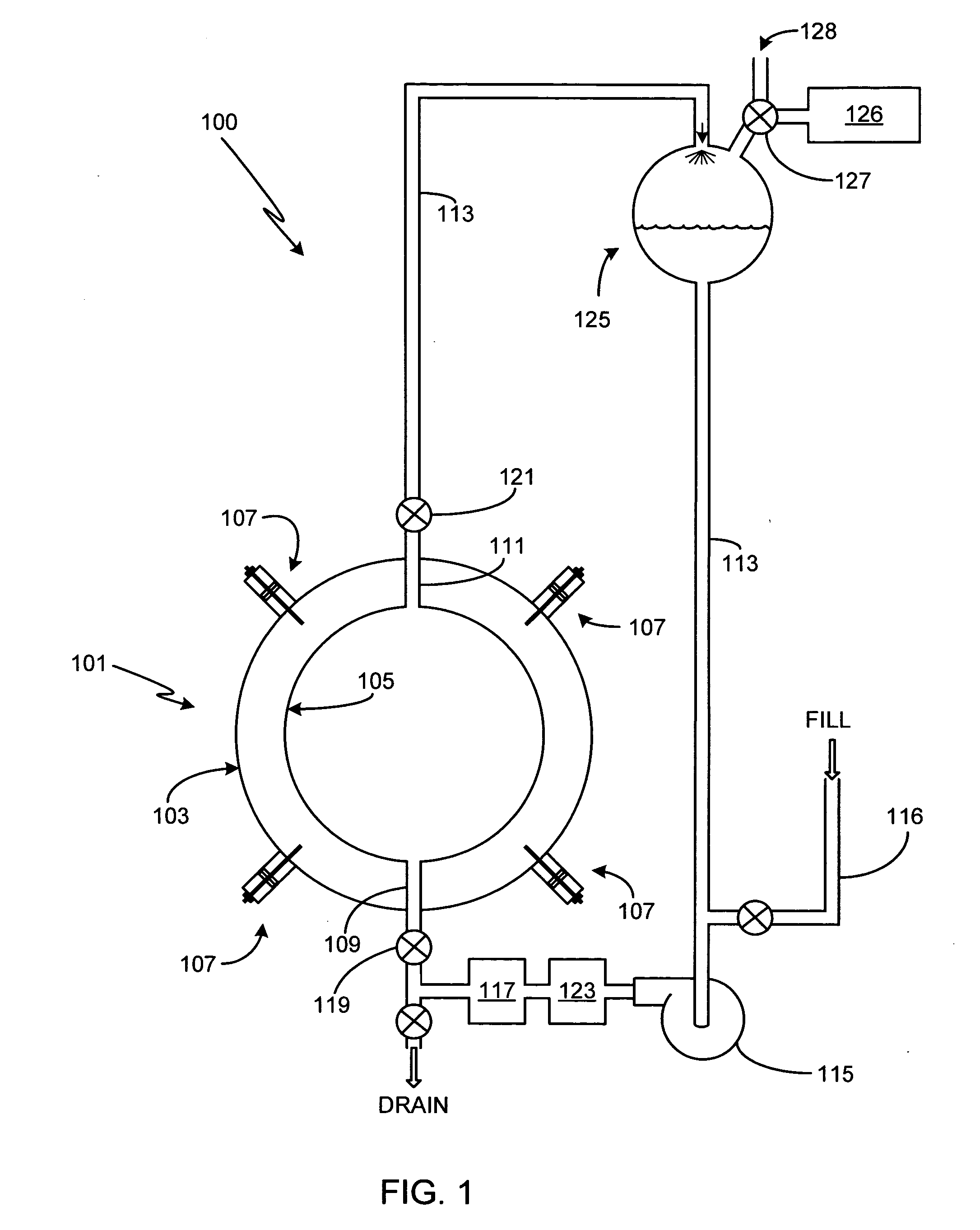
[0030]FIG. 1 is an illustration of the primary elements of a cavitation system 100 in accordance with the invention. The principal component is the sonoluminescence cavitation chamber 101, hereafter referred to as simply a cavitation chamber. Preferably cavitation chamber 101 is spherical, although it will be appreciated that the invention is not so limited and that cavitation chambers of other configurations (e.g., cylinder, conical, cubic, rectangular, irregular, etc.) can also be used with the present invention. One method of fabricating chamber 101 is described in detail in co-pending U.S. patent application Ser. No. 10 / 925,070, filed Aug. 23, 2004, entitled Method of Fabricating a Spherical Cavitation Chamber, the entire disclosure of which is incorporated herein for any and all purposes.

[0031] Illustrated chamber 101 has an outer spherical surface 103 defining the outer diameter of the chamber and an inner spherical surface 105 defining the inner diameter of the chamber. Cham...


PUM


Abstract

A method and apparatus for regulating the temperature of the cavitation medium for a cavitation chamber is provided. A heat exchange fluid is pumped through a heat exchange conduit that passes through a portion of the cavitation chamber. An external heat exchanger, coupled either directly or indirectly to the heat exchange conduit, regulates the temperature of the heat exchange fluid which, in turn, regulates the temperature of cavitation medium within the cavitation chamber. The heat exchanger can be used to lower the temperature of the cavitation medium to a temperature less than the ambient temperature; to withdraw excess heat from the cavitation medium; or to heat the cavitation medium to the desired operating temperature. The heat exchanger can utilize heated heat exchange fluid, cooled heat exchange fluid, thermoelectric coolers, heat sinks, refrigeration systems or heaters.

Description

REFERENCE TO RELATED APPLICATIONS [0001] This application is a continuation of U.S. patent application Ser. No. 10 / 961,353, filed Oct. 7, 2004, which is a continuation-in-part of U.S. patent application Ser. No. 09 / 448,753, filed Nov. 24, 1999.FIELD OF THE INVENTION [0002] The present invention relates generally to sonoluminescence and, more particularly, to a heat exchange system for use with a sonoluminescence cavitation chamber. BACKGROUND OF THE INVENTION [0003] Sonoluminescence is a well-known phenomena discovered in the 1930's in which light is generated when a liquid is cavitated. Although a variety of techniques for cavitating the liquid are known (e.g., spark discharge, laser pulse, flowing the liquid through a Venturi tube), one of the most common techniques is through the application of high intensity sound waves. [0004] In essence, the cavitation process consists of three stages; bubble formation, growth and subsequent collapse. The bubble or bubbles cavitated during thi...

Claims


Application Information

Patent Timeline
Patent Type & Authority Applications(United States)
IPC IPC(8): H05H1/22G21B1/00G21C1/00
CPCF24J3/00Y02E30/40F28D7/0041F28D7/106F28D21/00G21B1/00G21B3/00G21C1/00G21Y2002/301G21Y2002/302G21Y2002/304G21Y2002/40G21Y2004/30Y02E30/18Y02E30/30F28D7/0016F24V99/00Y02E30/10
Inventor TESSIEN, ROSS ALAN
Owner IMPULSE DEVICES INC
Why Eureka
Try Eureka