
System and method for heating, cooling and heat cycling on microfluidic device

a microfluidic device and heat cycling technology, applied in the field of integrated heaters and coolers on microfluidic devices, can solve the problems of limiting the diagnostic pcr, the dna isolation process in the past involved very tedious procedures, and the cost of traditional methods of isolation is high, and the problem of contamination becomes paramoun

Active Publication Date: 2009-03-26
PERKINELMER HEALTH SCIENCES INC
View PDF46 Cites 68 Cited by
  • Summary
  • Abstract
  • Description
  • Claims
  • Application Information

AI Technical Summary

Benefits of technology

[0016]In one embodiment, a microfluidic device is disclosed having a heating, cooling and heat cycling system on-board such that the device (e.g., in the form of a card) can be used portably. The microfluidic device includes one or more reservoirs containing exothermic or endothermic material. Once the chemical process of the reservoir material is activated, the

Problems solved by technology

Since PCR can amplify even a single molecule of DNA, problems of contamination become paramount.
The DNA isolation process in the past involved very tedious procedures and was a limiting factor for diagnostic PCR.
Although simplified, traditional methods of isolation require the use of expensive and cumbersome equipment, including for example a non-refrigerated centrifuge of at least 1300 rpm with relative centrifugal force (RCF) of about 16000 g is required since.
Although microfluidics has been used in a variety of applications, many technical issues with respect to performing the steps of isolation, amplification and detection remain for PCR to be effectively performed microfluidically.
One difficulty is integration of a thermal cycler.

Method used


Image

  • System and method for heating, cooling and heat cycling on microfluidic device
  • System and method for heating, cooling and heat cycling on microfluidic device
  • System and method for heating, cooling and heat cycling on microfluidic device

Examples


Embodiment Construction

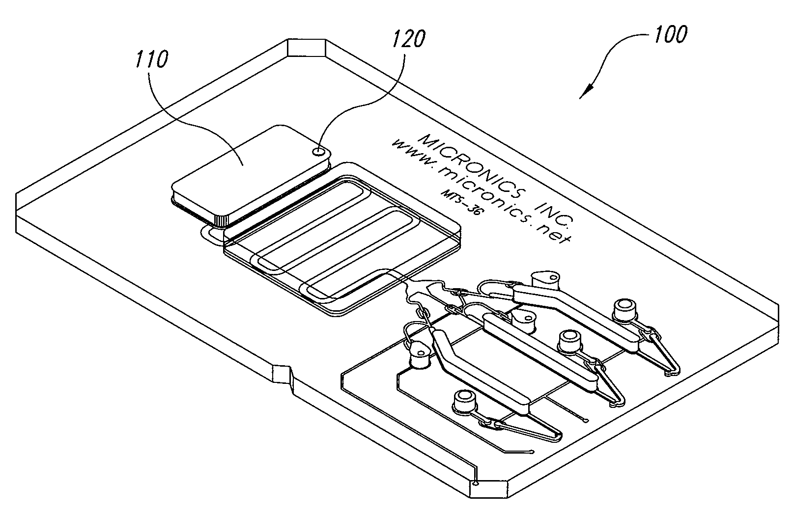
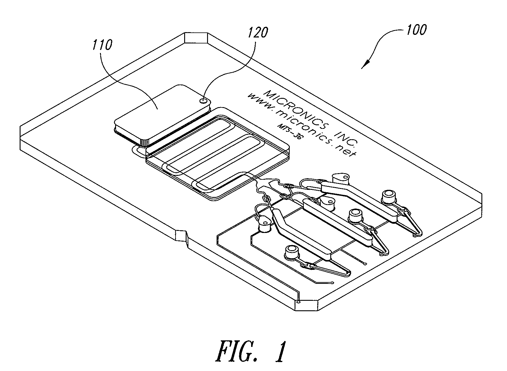
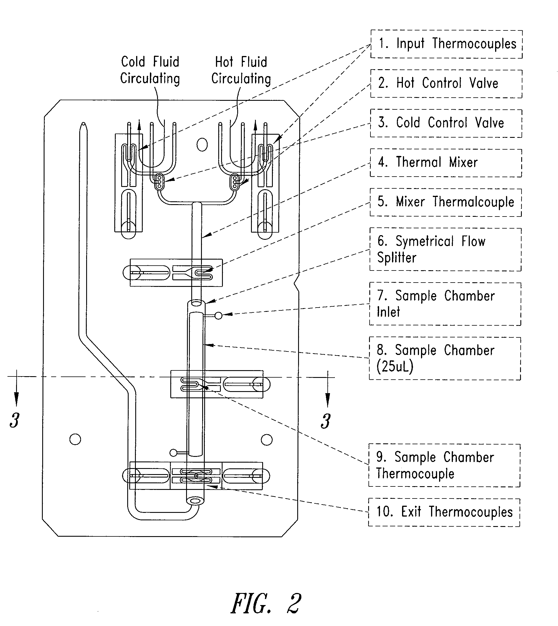
[0050]As noted above, the present invention is generally directed to a microfluidic device with a heating, cooling and heat cycling system on-board, a microfluidic device having an integrated heat exchanger circuit or a TEC used in connection with a microfluidic device to provide thermocycling.

[0051]According to one aspect of the invention, the portable microfluidic device is in the form of a card and has a heating, cooling and heat cycling system on-board such that the card can be used portably. (While generally discussed herein in the form of a planar “card”, the microfluidic device of this invention may take any number of physical forms.) The microfluidic card includes one or more reservoirs containing exothermic or endothermic material. Once the chemical process of the reservoir material is activated, the reservoir provides heating or cooling to specific locations of the microfluidic card. Multiple reservoirs may be included on a single card to provide varying temperatures. The ...


PUM


Abstract

An integrated heat exchange system on a microfluidic card. According to one aspect of the invention, the portable microfluidic card has a heating, cooling and heat cycling system on-board such that the card can be used portably. The microfluidic card includes one or more reservoirs containing exothermic or endothermic material. Once the chemical process of the reservoir material is activated, the reservoir provides heat or cooling to specific locations of the microfluidic card. Multiple reservoirs may be included on a single card to provide varying temperatures. The assay chemicals can be moved to the various reservoirs to create a thermal cycle useful in many biological reactions, for example, Polymerase Chain Reaction (PCR) or rtPCR. According to another aspect of the invention, the integrated heat exchanger is an adjacent microfluidic circuit containing fluid that is either independently heated or cooled, or is an exothermic or endothermic material, such that the fluid in the adjacent circuit imparts a change in temperature to the assay fluid in an independent circuit. According to yet another aspect of the invention, a thermal electric cooler (TEC) is used for thermocycling the amplification chamber of a disposable microfluidic card.

Description

CROSS-REFERENCE TO RELATED APPLICATIONS[0001]This is a continuation-in-part of U.S. patent application Ser. No. 10 / 862,826 filed Jun. 7, 2004 (now pending), which claims the benefit of U.S. Provisional Application No. 60 / 476,352, filed Jun. 6, 2003. Both of these applications are incorporated herein in their entireties.BACKGROUND OF THE INVENTION[0002]1. Field of the Invention[0003]This invention relates to an integrated heater and cooler on a microfluidic device for use in thermocycling, and more particularly, to a portable microfluidic card with a heating, cooling and heat cycling system on-board. This invention further relates to a microfluidic card having an integrated heat exchanger circuit, or thermal electric cooler (TEC) for use in connection with a microfluidic device to provide thermocycling for use in, for example, PCR or rtPCR.[0004]2. Description of the Related Art[0005]Integrated microfluidic handling systems that provide control over nanoliter sized volumes of liquid ...

Claims


Application Information

Patent Timeline
IPC IPC(8): C12M1/40
CPCB01L3/5027B01L7/52B01L2200/147B01L2300/1877B01L2300/0887B01L2300/1822B01L2300/185B01L2300/0816
Inventor BREIDFORD, WAYNE L.LANCASTER, CHRISTY A.HAYENGA, JON W.BARDELL, RONALD L.TONN, JEFFREY F.WEIGL, BERNHARD H.
Owner PERKINELMER HEALTH SCIENCES INC
Learn More