Phase-change refrigeration apparatus with thermoelectric cooling element and methods

a technology of phase-change refrigeration and thermoelectric cooling element, which is applied in the direction of refrigeration machines, lighting and heating apparatus, machines using electric/magnetic effects, etc. it can solve the problems of limited heat transfer capability of convectional heat transfer mechanisms, reduced data rate and/or operating frequency, and increased current consumption

Inactive Publication Date: 2005-01-25
INTEL CORP
View PDF15 Cites 80 Cited by
  • Summary
  • Abstract
  • Description
  • Claims
  • Application Information

AI Technical Summary

Problems solved by technology

As semiconductor devices, such as processors and processing elements, operate at continually higher data rates and higher frequencies they generally consume greater current and produce more heat.
Convectional heat transfer mechanisms have restricted t

Method used


Image

  • Phase-change refrigeration apparatus with thermoelectric cooling element and methods
  • Phase-change refrigeration apparatus with thermoelectric cooling element and methods
  • Phase-change refrigeration apparatus with thermoelectric cooling element and methods

Examples


Embodiment Construction

The following description and the drawings illustrate specific embodiments of the invention sufficiently to enable those skilled in the art to practice them. Other embodiments may incorporate structural, logical, electrical, process, and other changes. Examples merely typify possible variations. Individual components and functions are optional unless explicitly required, and the sequence of operations may vary. Portions and features of some embodiments may be included in or substituted for those of others. The scope of the embodiments of invention encompasses the full ambit of the claims and all available equivalents.

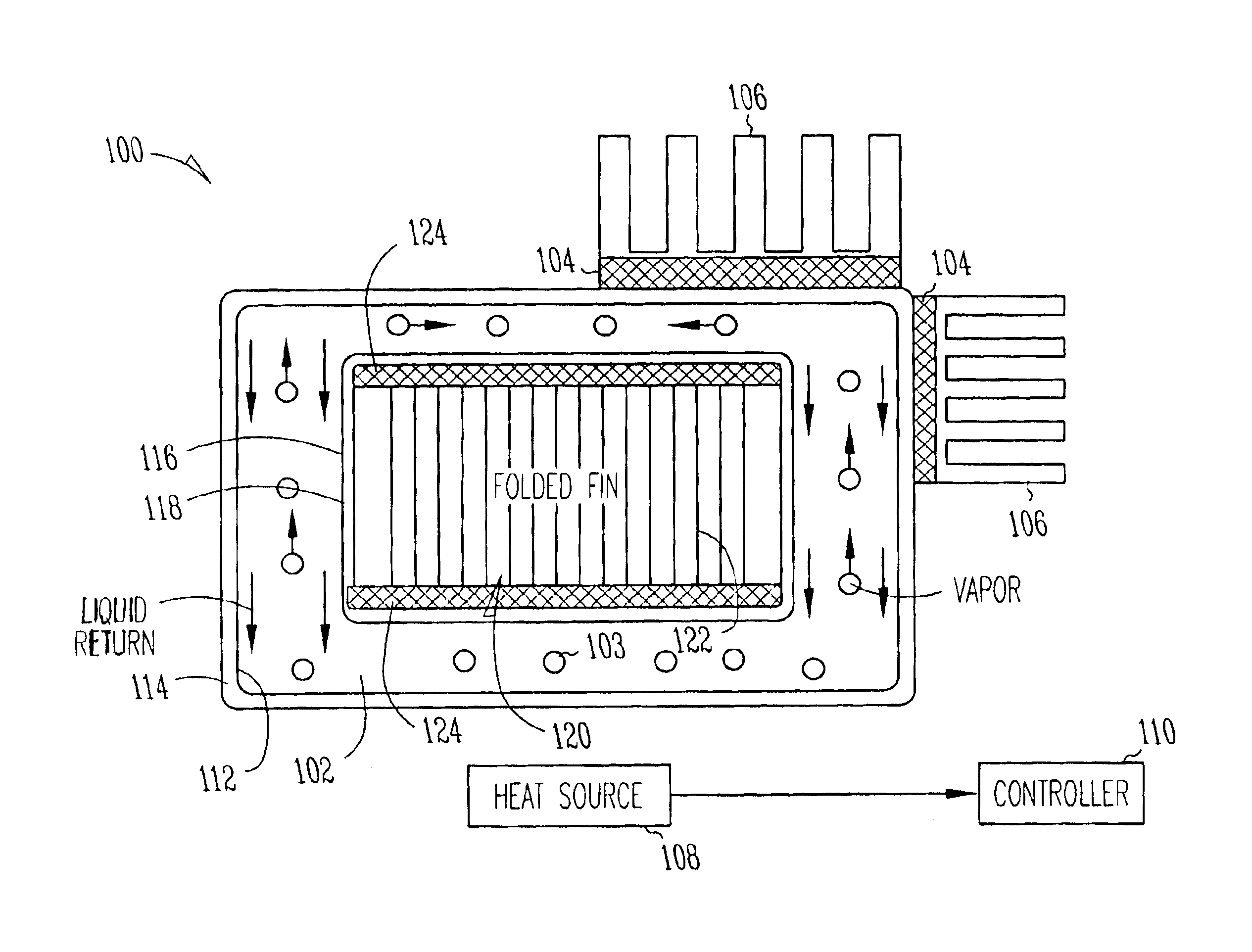
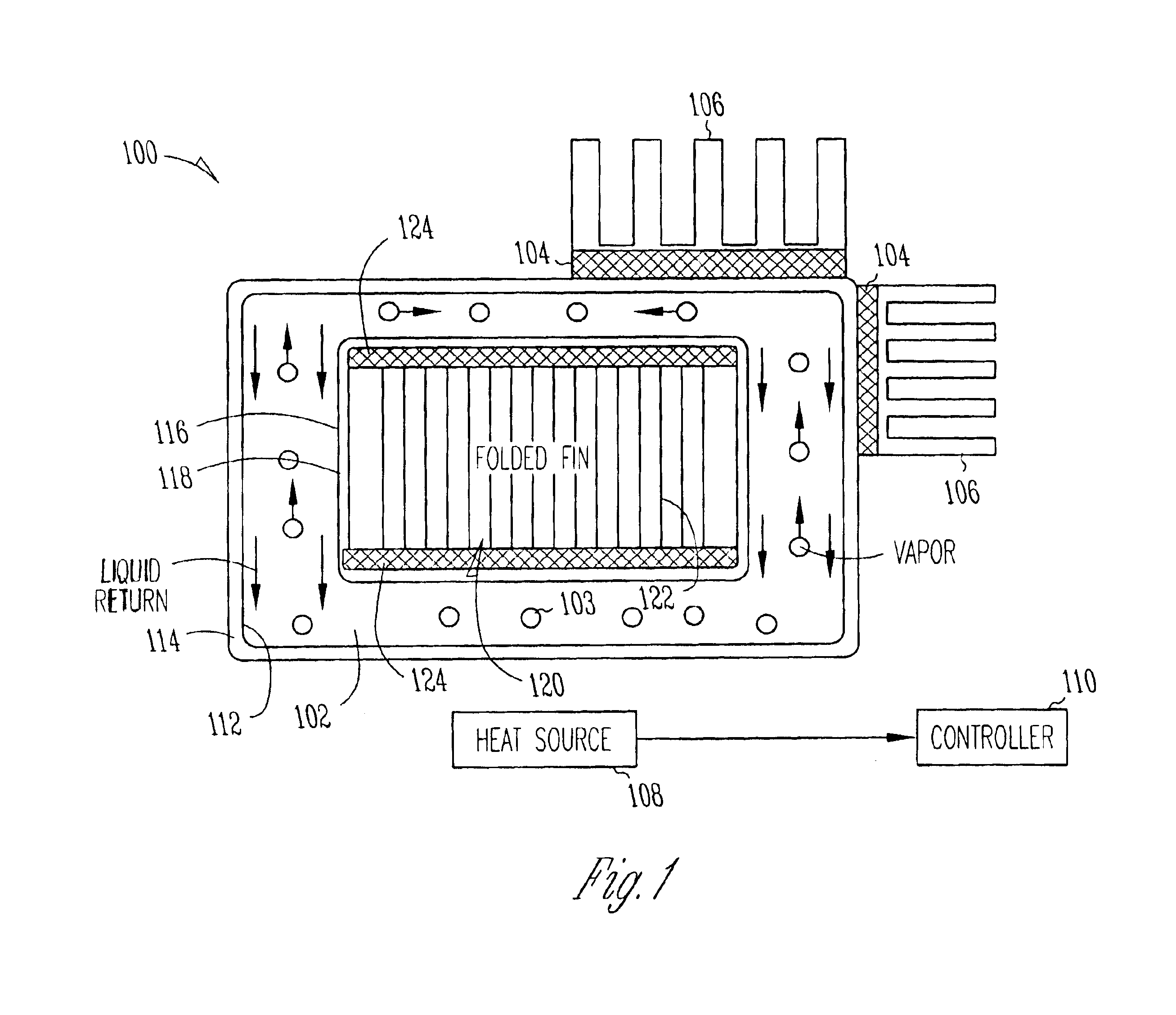
In embodiments, the present invention provides a heat-transfer device having a sealed vapor chamber with a phase-change fluid therein. The heat-transfer device includes a thermoelectric cooling (TEC) element with a cooled side in thermal contact with the vapor chamber and a heated side in contact with heat-dissipation fins. The TEC element may decrease the temperature o...


PUM


Abstract

A heat-transfer device has a sealed vapor chamber with a phase-change fluid therein, and a thermoelectric cooling (TEC) element with a cooled side in thermal contact with the vapor chamber and a heated side in contact with heat-dissipation fins. The TEC element decreases the temperature of the vapor chamber and increases the temperature of the fins for improved efficiency. The vapor chamber is defined between concentrically positioned tubes, and a tunnel region is located within the inner tube. Additional TEC elements within the tunnel region further dissipate heat. In two-phase natural convection embodiments, TEC elements may further cool liquid returning to the heat source. Parallel heat dissipation paths may also be provided. In a two-phase forced convection embodiment, a TEC element may further cool liquid returning to the heat source, and additional TEC elements may be provided on the condenser. In some embodiments, active feedback controls the amount of energy transferred by a TEC element.

Description

TECHNICAL FIELDThe present invention pertains to heat transfer mechanisms for integrated circuits.BACKGROUNDAs semiconductor devices, such as processors and processing elements, operate at continually higher data rates and higher frequencies they generally consume greater current and produce more heat. It is desirable to maintain operation of these device within certain temperature ranges for reliability reasons, among others. Convectional heat transfer mechanisms have restricted the operation of such devices to lower power levels, lower data rates and / or lower operating frequencies. Convectional heat transfer mechanisms have limited heat transfer capability due to size and location restrictions, as well as thermal limitations.Thus what is need are improved heat transfer apparatus and methods suitable for semiconductor devices. What are also needed are heat transfer apparatus and methods that lower the operating temperature of processors. What are also needed are heat transfer appar...

Claims


Application Information

Patent Timeline
IPC IPC(8): F25B21/02F28D15/02H01L35/00H01L35/28H01L35/30
CPCF25B21/02H01L35/30F28D15/0275H01L35/00F28D15/0266F25B2321/0212H10N10/00H10N10/13
Inventor SAUCIUC, IOANCHRYSLER, GREGORY M.
Owner INTEL CORP
Why Eureka
Try Eureka